
Combined battery device

A technology of combining batteries and single cells, applied in battery circuit devices, circuit devices, batteries, etc., can solve the difficulty of stopping charging, the internal temperature of the single battery is not the same as the surface temperature, the surface temperature of the single battery is easily affected by the surrounding temperature, etc. question

Inactive Publication Date: 2005-09-21
GS YUASA INT LTD
View PDF1 Cites 2 Cited by
  • Summary
  • Abstract
  • Description
  • Claims
  • Application Information

AI Technical Summary

Problems solved by technology

However, this method has the following disadvantages: usually the internal temperature of the single cell is different from the surface temperature, and the surface temperature of the single cell is easily affected by the ambient temperature, so it is necessary to correctly grasp the internal temperature of the single cell and stop charging. more difficult
In addition, in the above-mentioned structure, in order to install the switch, it is also necessary to ensure the distance between the inner wall surface of the container and the unit cells, and there is a possibility that the overall size will increase, and the installation space will also need to be considerably large.

Method used


Image

  • Combined battery device
  • Combined battery device
  • Combined battery device

Examples


no. 2 Embodiment

[0035] Regarding the second embodiment of the embodied power supply device of the present invention, refer to Figure 5 Be explained. In this embodiment, the same parts as those in the first embodiment are assigned the same symbols, and redundant descriptions are omitted.

[0036] This embodiment differs from the first embodiment in that push button switches 71 with normally open contacts are used and connected in parallel with each other, and a relay switch 63B with normally closed contacts is used in the charging stop circuit 6 .

[0037] No matter which single battery 10 in this embodiment does not reach the overcharged state and does not cause expansion and deformation, the button switch 71 is in the open state, and there is no current in the relay coil 63A, so the power consumption can be reduced.

no. 3 Embodiment

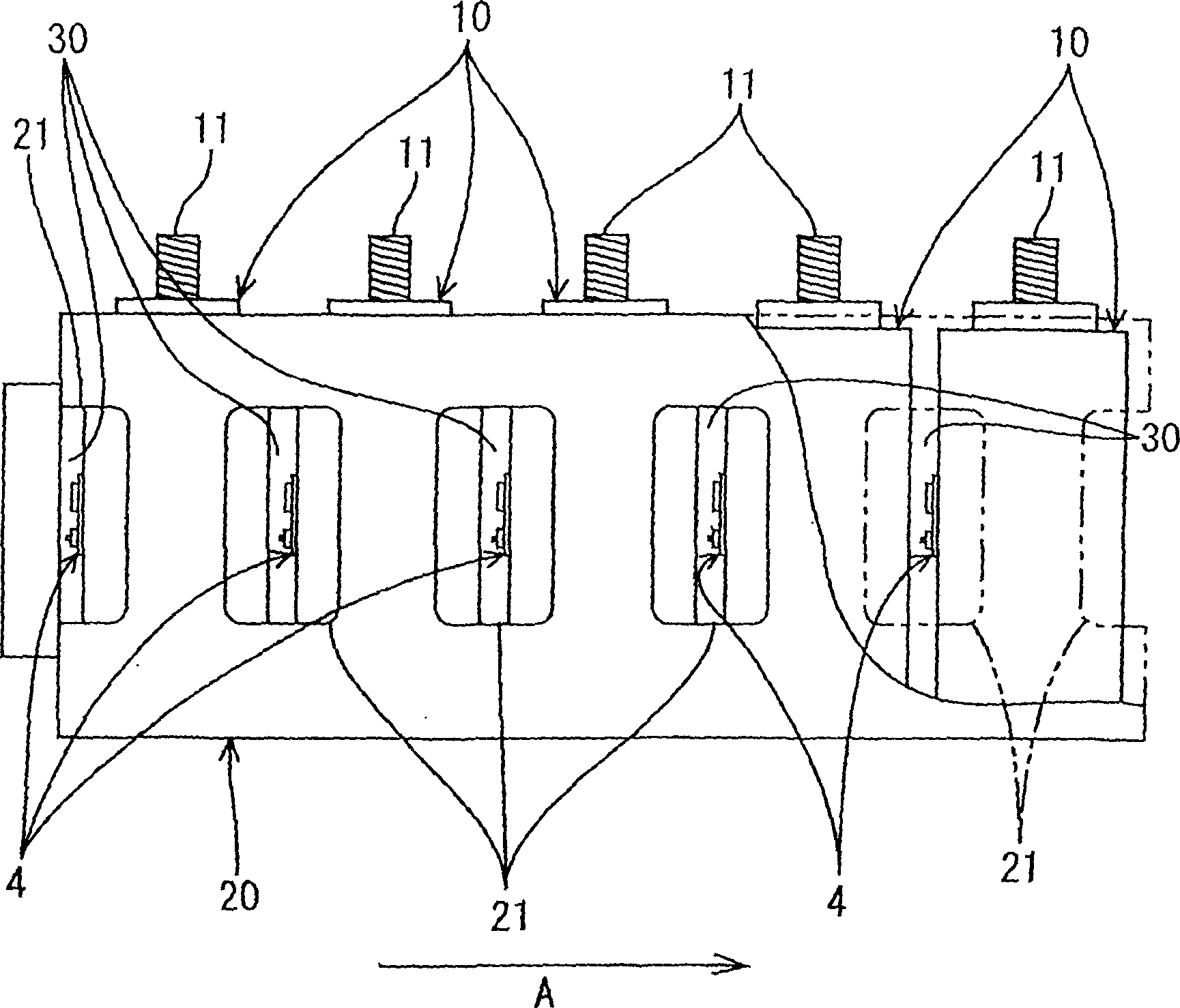
[0039] Regarding the 3rd embodiment of the power supply device of the embodiment of the present invention, refer to Figure 6 and Figure 7 To illustrate. In this embodiment, the same parts as those in the first embodiment are assigned the same symbols, and redundant descriptions are omitted. Meanwhile, descriptions of the same action and effect are also omitted.

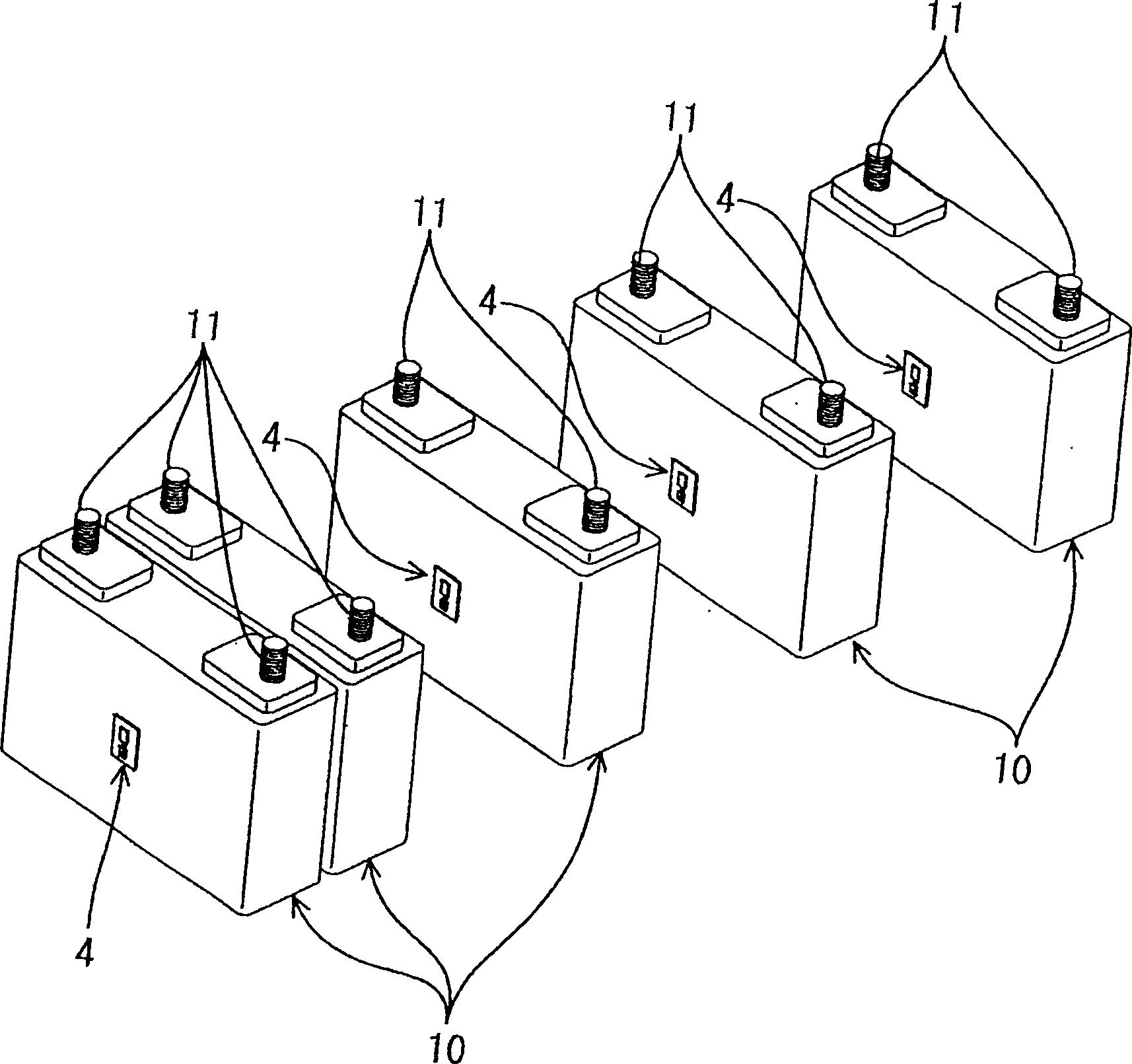
[0040] In this embodiment, the arrangement of the cells 10 is different from that of the first embodiment. That is, compared to the first embodiment ( figure 2 The arrangement of cells 10 in reference) is a so-called one-dimensional arrangement in which they are arranged in a row from front to back. In this embodiment, four cells 10 are arranged in two rows from front to rear, which is a so-called two-dimensional arrangement. In addition, the circuit board 4 is fixed to the central portion of the front side wall of the battery cell 10 located on the rear side of the battery cells 10 adjacent to the front and ba...


PUM


Abstract

An assembled battery device comprising a plurality of single cells which are placed with a predetermined space between each of them and an element for detecting swelling is set in the predetermined space between the single cells and operates in accordance with the transformation of the single cells by swelling. Therefore, when a single cell swells and transforms, resulting from being overcharged, the element for detecting swelling is activated in accordance with such transformation and detects the state of overcharging.

Description

technical field [0001] The present invention relates to an assembled battery device composed of a plurality of single batteries. Background technique [0002] Generally speaking, as a rechargeable battery that can be repeatedly charged and discharged, an assembled battery composed of a plurality of single cells can be used according to the load. When this combined battery is being charged, if the single cell is in an overcharged state, it will cause the adverse effect of shortening the life of the single cell. Therefore, it is very necessary to prevent the overcharging of each single cell when charging. [0003] When a single cell is in an overcharged state, for example, even if the charging voltage of the single cell rises above the rated voltage, it will cause abnormal heating of the single cell, or the electrode plate inside the single cell will expand and the single cell Extrusion of the surface causes changes in the expansion deformation of the surface. Therefore, by ...

Claims


Application Information

Patent Timeline
Patent Type & Authority Patents(China)
IPC IPC(8): H01M6/42H01M6/50H01M10/44H01M10/48H01M50/569H02J7/00
CPCH01M2/0217H02J7/0026H01M2200/20H01M2/345H01M10/48H01M6/42H01M10/44H02J7/0063H02J7/0013Y02E60/10H01M50/103H01M50/578H02J7/00302H02J7/00714H01M50/569
Inventor 增田英树田才博志西山浩一
Owner GS YUASA INT LTD
Learn More