Video frequency decoding and channel trapping system

A channel and video technology, applied in high-definition television systems, components of television systems, two-way working systems, etc., to achieve the effect of reducing delays

Inactive Publication Date: 2005-10-05
INTERDIGITAL CE PATENT HLDG
View PDF0 Cites 0 Cited by
  • Summary
  • Abstract
  • Description
  • Claims
  • Application Information

AI Technical Summary

Problems solved by technology

Also, channel changes may require repeated phase lock and equalization operations if the newly selected channel is in a data stream transmitted on a different transponder or RF channel

Method used


Image

  • Video frequency decoding and channel trapping system
  • Video frequency decoding and channel trapping system
  • Video frequency decoding and channel trapping system

Examples


Embodiment Construction

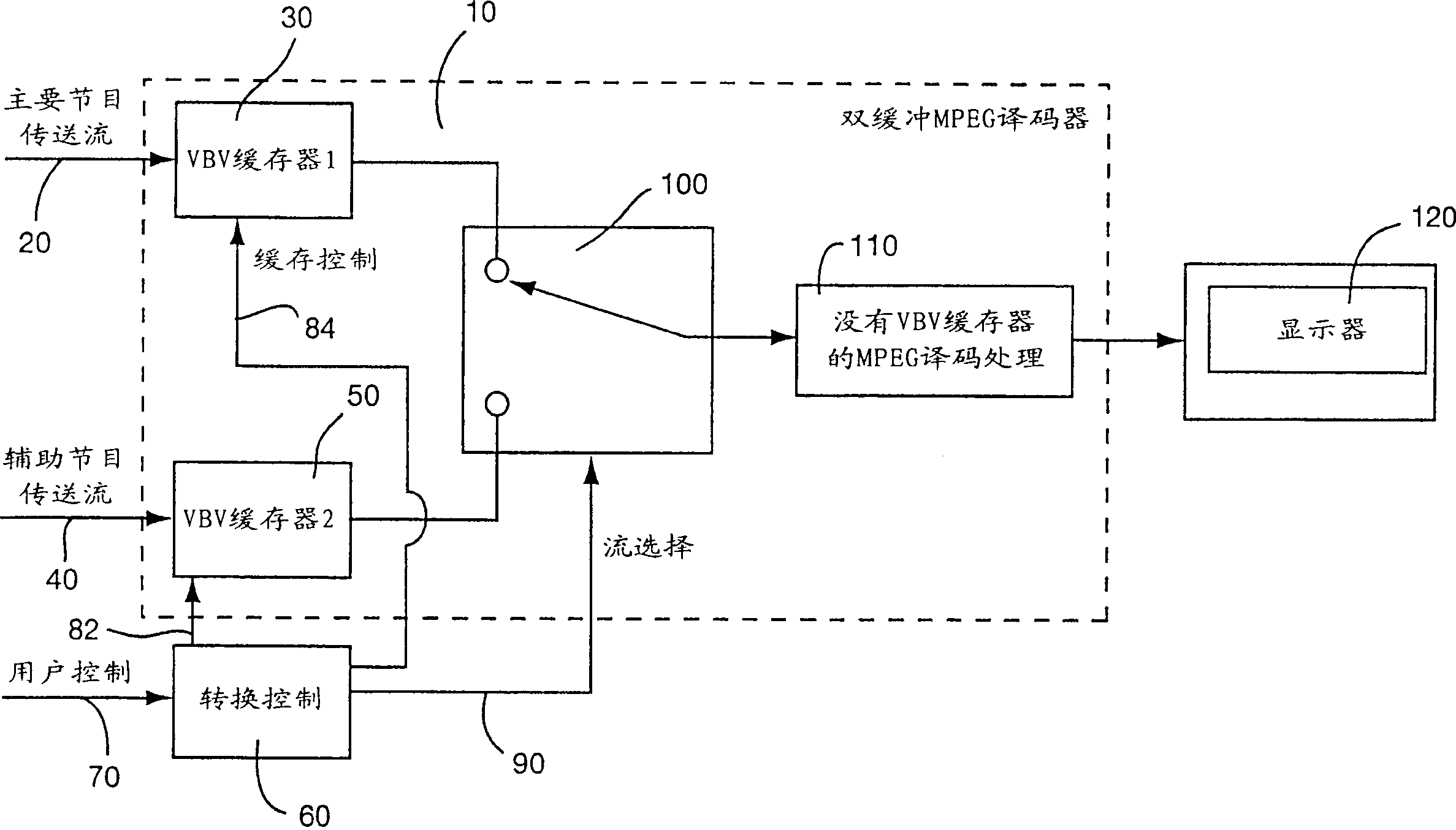
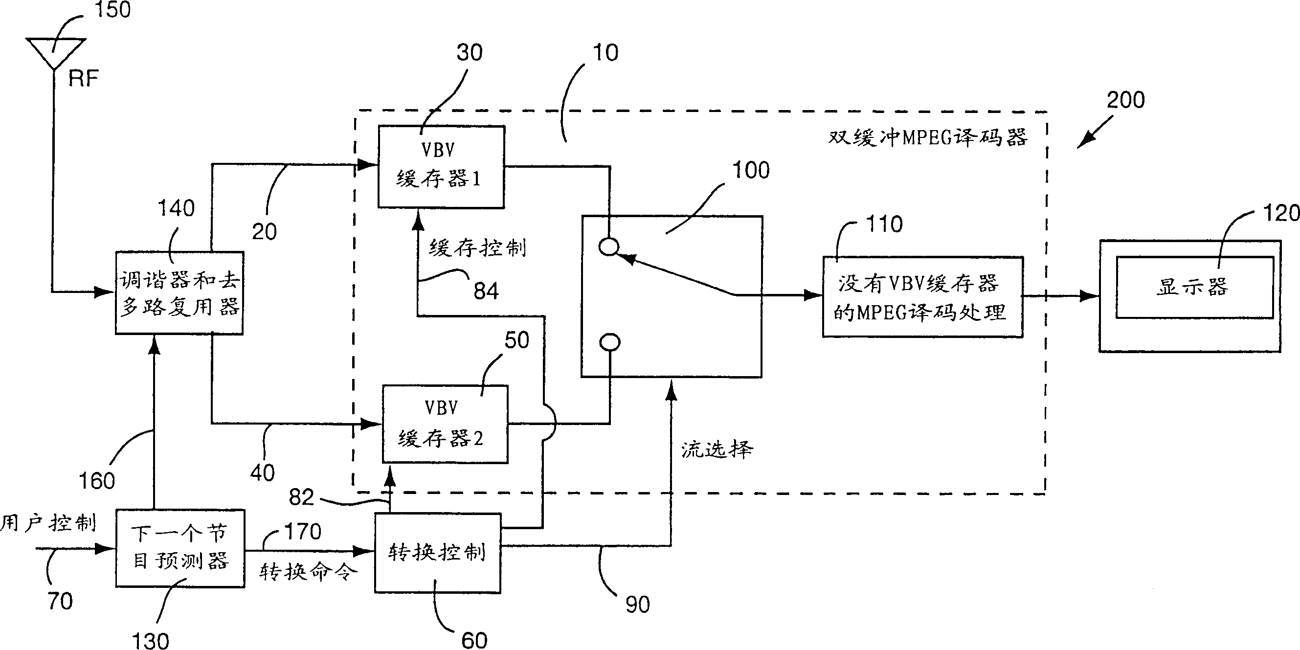
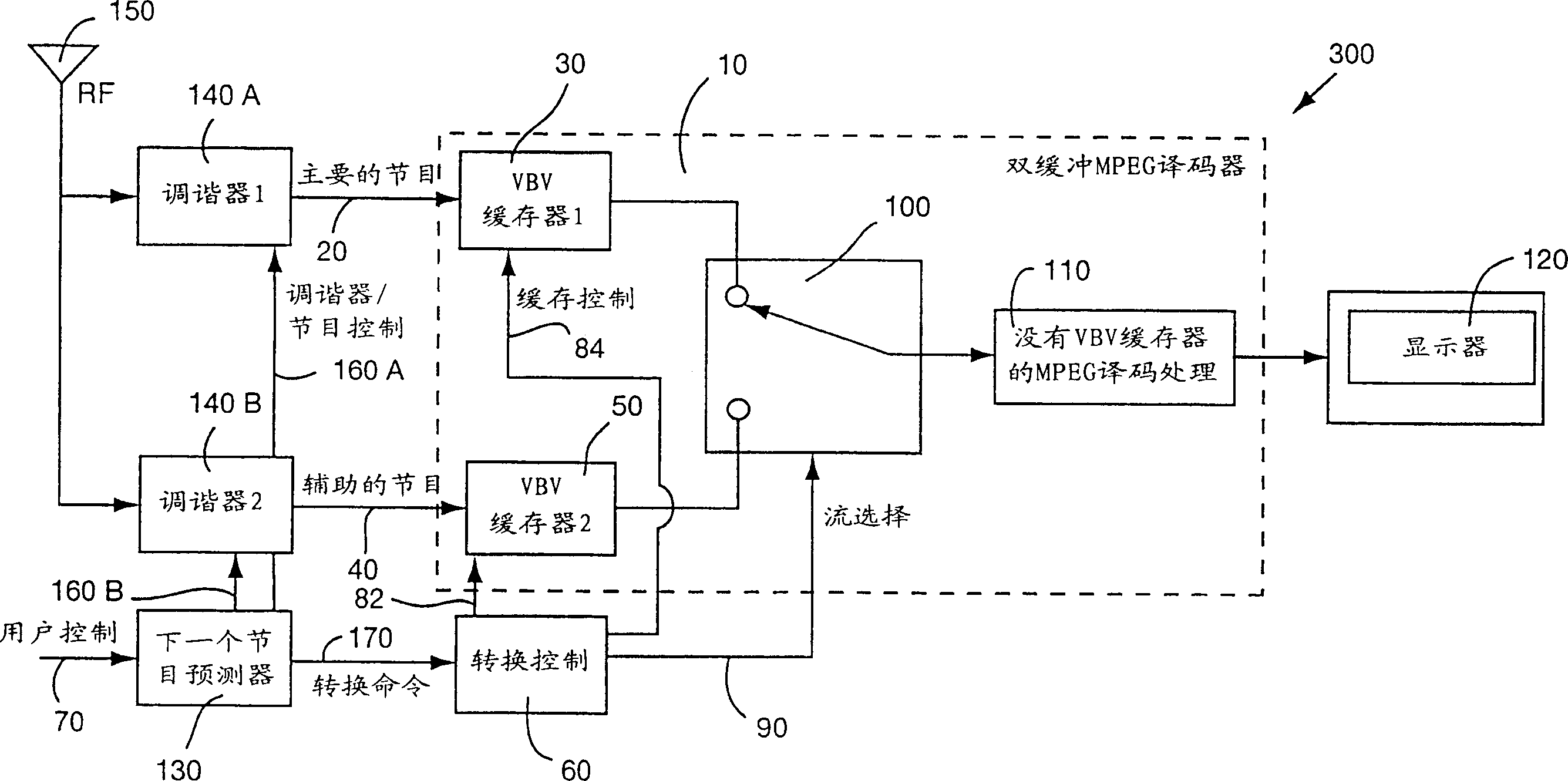
[0012] The system of the present invention uses multiple tuners such that while one tuner is used to process and display the current program, another tuner is used to obtain other programs. However, it is not desirable to use a second full set of tuners and decoders dedicated to picture-in-picture (PIP) applications due to the additional cost and delay involved in decoder setup and initialization.

[0013] According to the present invention, undesired delays associated with user channel changes can be significantly reduced by pre-buffering a data stream comprising programs transmitted on the newly selected channel. In particular, pre-buffering reduces the delay in obtaining I-frames in a new data stream and capturing enough data to fill the buffer to the MPEG-specified VBV buffer occupancy level. By pre-buffering the incoming data, once the user initiates a channel change, the I-frame entry point for selection can be obtained and the buffer filled to the required MPEG occupanc...


PUM


Abstract

A digital video decoding system receives packetized video data representing programs conveyed on a plurality of video channels. The system includes a plurality of buffers (30, 50) for storing encoded video data representing images of video programs conveyed on a corresponding plurality of video channels. An individual buffer, corresponding to an individual video channel, stores sufficient encoded video data to prevent an underflow condition following switching to decode a program conveyed on the individual video channel. A processor (60) initiates switching to decode a program conveyed on a selected one of the plurality of video channels in response to a user channel selection input (70). A decoder (110) decodes encoded video data received from one of the plurality of buffers corresponding to the program conveyed on the selected video channel as determined by switching initiated by the processor. The decoder also predicts (130) a next channel to be selected by a user.

Description

technical field [0001] The present invention relates to digital video systems, and more particularly to an improved digital video receiver and method of receiving digital video signals. Background technique [0002] Digital television systems and receivers have proliferated rapidly over the past few years. Some examples include DIRECTV, DVB (Digital Video Broadcasting Project) and ATSC (Advanced Television Systems Committee) type systems. Due to the considerable amount of data associated with video communications, compression has become an integral part of most modern digital video applications. [0003] The Moving Picture Experts Group has defined a standardized video compression method called the MPEG (Moving Pictures Experts Group) picture coding standard for video signals and pictures, hereinafter referred to as "MPEG standard". The MPEG standard includes a system coding part (ISO / IEC 13818-1, June 10, 1994) and a video coding part (ISO / IEC 13818-2, January 20, 1995). ...

Claims


Application Information

Patent Timeline
Patent Type & Authority Patents(China)
IPC IPC(8): H04N5/455G06T9/00H04H20/00H04H40/18H04N5/44H04N5/50H04N7/173H04N7/32H04N19/50H04N21/234H04N21/433H04N21/438H04N21/44H04N21/442H04N21/475
CPCH04N21/23424H04N21/4383H04N21/4755G06T9/004H04N21/44016H04N21/44222H04N21/4384H04N5/50H04N21/44004H04N21/23406H04N5/4401H04N21/426H04N7/24H04N5/44
Inventor 小罗伯特·N·赫斯特
Owner INTERDIGITAL CE PATENT HLDG
Why Eureka
Try Eureka