Cathod-ray tube

A technology for cathode ray tubes and coils, applied in the direction of cathode ray tubes/electron beam tubes, discharge tubes, electrode devices and related components, etc., which can solve the problems of increasing the number of components, deteriorating the heating performance of deflection yokes, reducing efficiency and productivity, etc.

Inactive Publication Date: 2005-11-09
MERIDIAN SOLAR & DISPLAY
View PDF0 Cites 0 Cited by
  • Summary
  • Abstract
  • Description
  • Claims
  • Application Information

AI Technical Summary

Problems solved by technology

However, increasing the horizontal deflection current deteriorates the heat generation inside the deflection yoke, thus degrading the quality of the deflection yoke
[0025] Second, as shown in Figure 5, when the degaussing coil is used to reduce the leakage magnetic field, a ringing (ringing) 49 is produced on the screen 48
Thus, increasing the number of elements that need to operate, reducing its efficiency and productivity
[0027] Fourth, the degaussing coils 37a and 37b must be prepared and installed
[0033] As mentioned above, it is difficult to reduce the leakage magnetic field in a general deflection yoke and a deflection yoke for obtaining a high deflection angle

Method used


Image

  • Cathod-ray tube
  • Cathod-ray tube
  • Cathod-ray tube

Examples


Embodiment 1

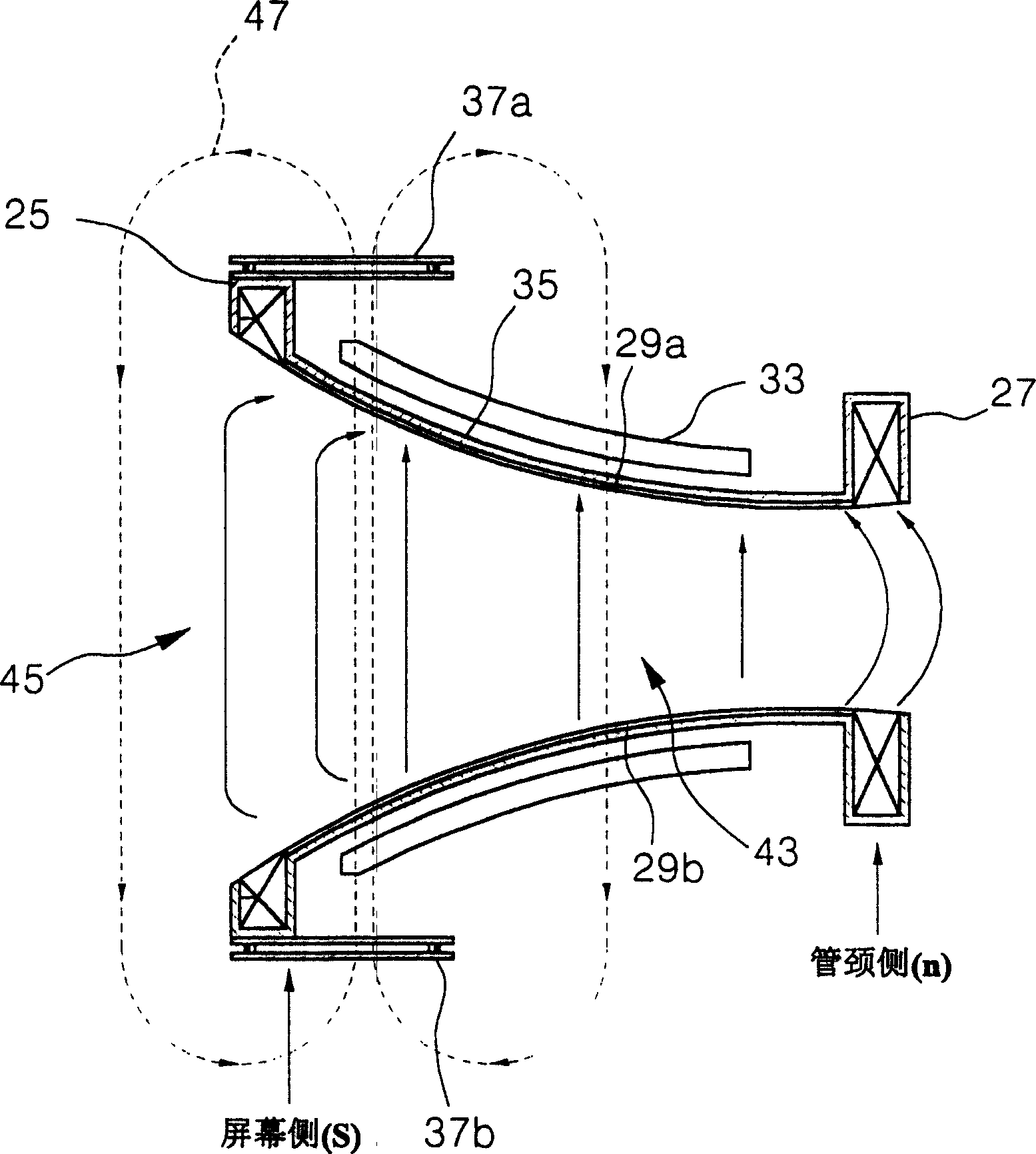
[0056] Figure 6 is a schematic structural view showing a deflection yoke according to the invention. Such as Figure 6 As shown, the deflection yoke comprises a horizontal deflection coil 51 on the screen side, and a ferrite core 57 between the screen side (s) and the neck side (n). Here, the base 55 is installed between the horizontal deflection coil 51 and the ferrite core 57 for insulating them, and the vertical deflection coil 53 is installed between the base 55 and the ferrite core 57 . Therefore, the sequence of element arrangement inside the deflection yoke is the horizontal deflection coil 51, the base 55, the vertical deflection coil 53 and the ferrite core 57. The deflection yoke is preferable to reduce the diameter of the end of the ferrite core near the screen side and to reduce the length of the ferrite core in the tube axis direction.

[0057] When the ferrite core 57 is fixed on the outer surface of the seat 55, the installation position of the end of the neck...

Embodiment 2

[0080] In the present invention ( Figure 10A ) and prior art ( Figure 10B ) shows the positional relationship between the ferrite core and the horizontal deflection coil in the deflection yoke where TPS has been adopted. deflection yoke using TPS with Figure 7A and Figure 7B The deflection yoke has the same concept and principle.

[0081] According to the scanning method used in ordinary CRTs, if viewed from a screen, electron beams from an electron gun scan from left to right to configure the screen. However, according to the scanning method used for the TPS type CRT, if viewed from the screen, electron beams emitted from the electron gun scan from top to bottom or bottom to top to configure the screen. In short, the scanning method used in the TPS type CRT is different from the conventional scanning method in that it scans by an electron beam rotated by 90 degrees. Therefore, compared with the electron beam array of the electron gun of the common CRT, the electron b...

Embodiment 3

[0085] Example 3 to explain.

[0086] [Example 3]

[0087] Embodiment 3 The deflection yoke with a high deflection angle greater than 110° and Figure 7A and Figure 7B The deflection yoke has the same principle.

[0088] Such as Figure 7A and Figure 7B As shown, that is to say, in the deflection yoke with high deflection angle greater than 110°, the interval between the end of the horizontal deflection coil near the screen side and the end of the ferrite core near the screen side is the horizontal deflection coil in the tube 27% to 50% of the length Lh in the axial direction.

[0089] Furthermore, in the deflection yoke with a high deflection angle of more than 110°, the diameter Rc of the end of the ferrite core near the screen side is 50% to 85% of the diameter of the end of the horizontal deflection coil near the screen side.

[0090] The leakage magnetic field was measured by using the range of conditions shown in Table 1, which was lower than 20 nT.

[0091] ...


PUM


Abstract

The present invention discloses a cathode ray tube including a deflection yoke which can remarkably decrease a leakage magnetic field. In the deflection yoke, a diameter of an end of a ferrite core to a screen side is 50% to 85% of a diameter of an end of a horizontal deflection coil to the screen side, and an interval between the end of the horizontal deflection coil to the screen side and the end of the ferrite core to the screen side is 27% to 50% of a length of the horizontal deflection coil in a tube axis direction. As a result, the cathode ray tube can overcome problems of general cancel coils, and reduce the leakage magnetic field even at a high deflection angle.

Description

technical field [0001] The present invention relates to a cathode ray tube, and more particularly, to a cathode ray tube having a deflection yoke capable of reducing a leakage magnetic field. Background technique [0002] In general, television sets or other image display devices utilizing cathode ray tubes include deflection yokes for deflecting electron beams generated by electron guns. [0003] Here, there is one electron gun in a black and white cathode ray tube, while a color cathode ray tube includes three electron guns arranged in a horizontal line for the purpose of reproducing a color image by mixing red R, green G, and blue B. [0004] A color cathode ray tube employs a self-converging deflection yoke utilizing an irregular magnetic field. Its purpose is to converge the three R, G and B electron beams emitted from the electron gun into one point on the phosphor screen. [0005] Here, the pincushion-shaped horizontal deflection magnetic field or the cylindrical ve...

Claims


Application Information

Patent Timeline
Patent Type & Authority Patents(China)
IPC IPC(8): H01J29/76
CPCH01J29/76H01J2229/7031
Inventor 李锡文
Owner MERIDIAN SOLAR & DISPLAY
Why Eureka
Try Eureka