Loudspeaker for electronic apparatus

A speaker and terminal connection technology, applied in the field of speakers, can solve problems such as terminal detachment

Inactive Publication Date: 2005-11-09
CITIZEN ELECTRONICS CO LTD
View PDF0 Cites 0 Cited by
  • Summary
  • Abstract
  • Description
  • Claims
  • Application Information

AI Technical Summary

Problems solved by technology

[0016] However, when the above-mentioned various conventional sound generators are dropped on a hard ground and collide with the ground, the coil spring 59 or the spring plate 62 will be disengaged from the terminals.
Also, in order to precisely weld coil springs or spring plates, multiple jigs must be set, which requires multiple manufacturing steps

Method used


Image

  • Loudspeaker for electronic apparatus
  • Loudspeaker for electronic apparatus
  • Loudspeaker for electronic apparatus

Examples


Embodiment Construction

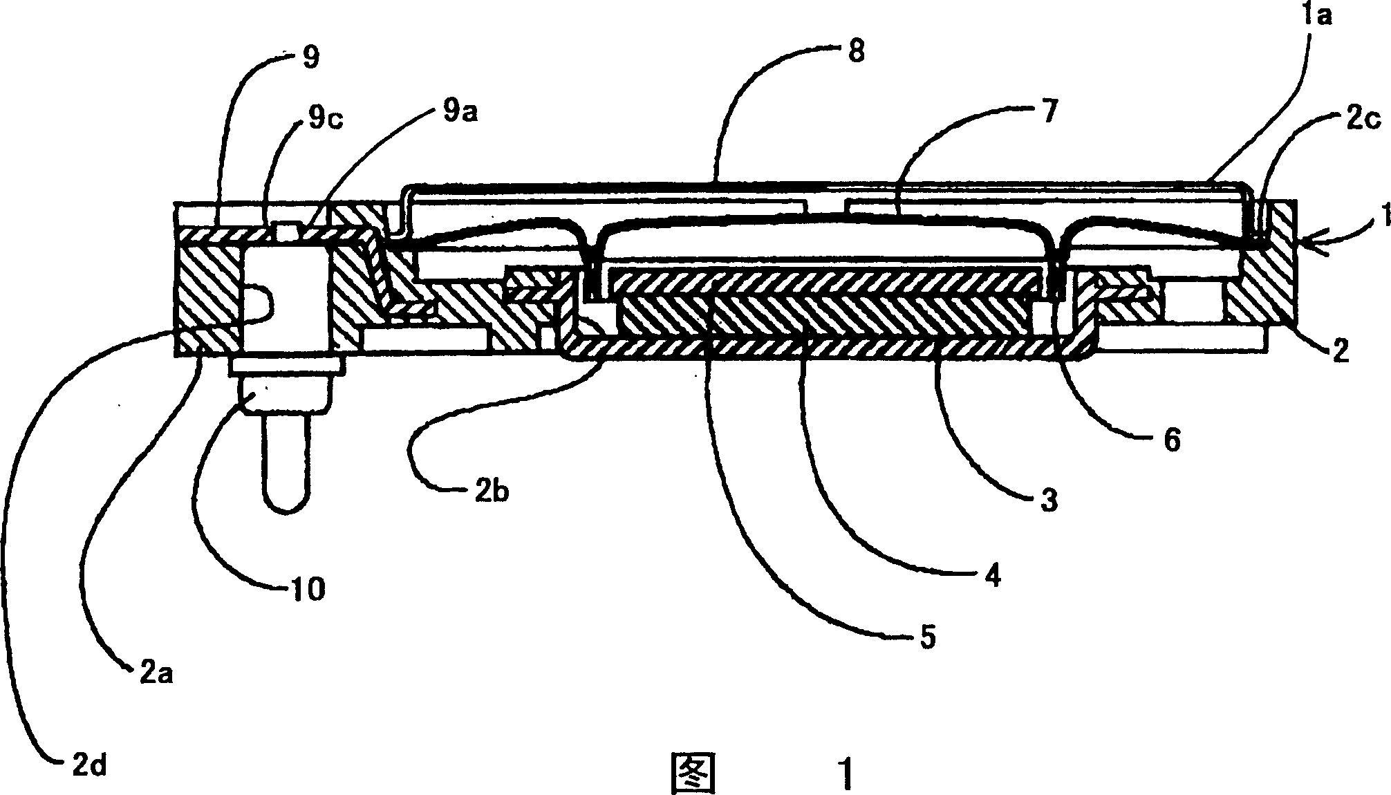
[0031] Referring to Fig. 1, shown in the figure is the sectional view of loudspeaker of the present invention, loudspeaker body and Figure 5 and 6 Same construction as conventional loudspeaker shown. That is, the speaker 1 has a frame 2 .

[0032] Formed on the frame 2 are a cubic portion 2a, a central circular hole 2b and a boss 2c.

[0033] A yoke 3 made of magnetic material is embedded in the frame 2 . A circular magnet 4 and a top plate 5 are mounted on the yoke 3 . A circular vibrating plate 7 with a voice coil 6 is fixed on the boss 2c. Thus, a magnetic circuit is formed by the yoke 3, the magnet 4 and the vibrating plate 7.

[0034] A pair of terminal blocks 9 are embedded in the frame 2 .

[0035] Each terminal plate 9 extends between an end portion 9a exposed in the hole 2d and an end of the coil 6 . The end portion 9a has a hole 9c in the center.

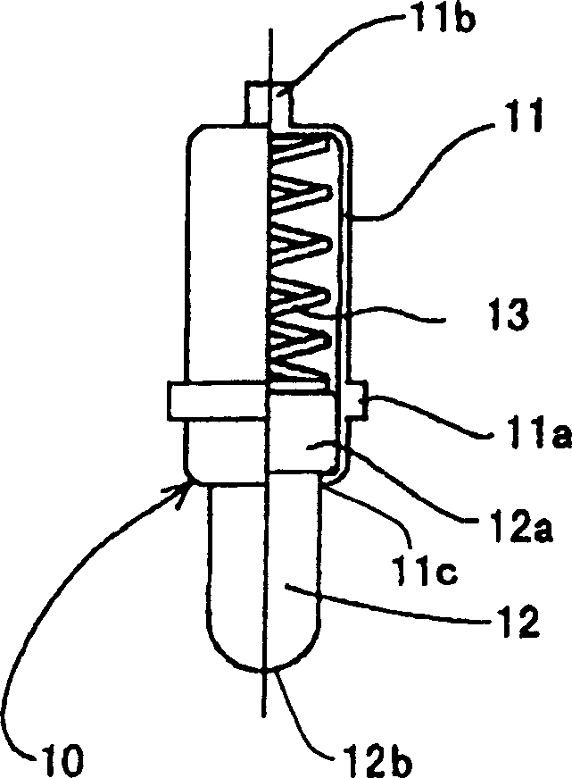
[0036] According to the present invention, there is a terminal connecting device 10 to be inserted into the hole...


PUM


Abstract

A speaker has a frame provided with a yoke, a magnet, a vibrating plate and a voice coil, and a pair of leads. An end of each of the leads is connected to an end of the coil and the other end portion of the lead is exposed in a hole formed in the frame and secured to the frame so as to be connected to an outside terminal. A terminal connecting device is provided for connecting the other end of the lead to the outside terminal. The terminal connecting device comprises a cylindrical case secured in the hole of the frame, a connecting rod slidably mounted in the cylindrical case, and a coil spring provided in the cylindrical case to outwardly urge the connecting rod so as to be contacted with the outside terminal at an end of the rod. A top end of the cylindrical case is contacted with the end portion of the lead.

Description

technical field [0001] The present invention relates to a speaker that emits sound by vibrating a vibrating plate by an electromagnetic member, and more particularly, to an electrodynamic speaker mounted on a printed circuit board of an electronic device such as a mobile phone. Background technique [0002] In recent years, the mounting of small electronic components on printed circuit boards has become more and more frequent, so electrodynamic speakers for small electronic devices are mounted on printed circuit boards. Printed circuits for mobile phones are used as means for generating signals. [0003] see Figure 5 and 6 , the figure shows a plan view of a conventional dynamic loudspeaker, and along the Figure 5 A sectional view of the center line VI-VI, the dynamic speaker 50 has a circular frame 51 having a central circular hole 51b and a cubic portion 51a. An annular boss 51c is formed on the frame 50, and a pair of cylindrical holes 51d are formed on the cubic port...

Claims


Application Information

Patent Timeline
Patent Type & Authority Patents(China)
IPC IPC(8): H04R9/02H04R9/06
CPCH04R9/06H04R1/00
Inventor 太田良纯
Owner CITIZEN ELECTRONICS CO LTD
Why Eureka
Try Eureka