Supercharge Your Innovation With Domain-Expert AI Agents!

Laser scanner and copier therewith

A technology of laser scanners and copiers, applied in printing, optics, instruments, etc., can solve problems such as incorrect printing

Inactive Publication Date: 2005-11-23
TOSHIBA TEC KK
View PDF1 Cites 0 Cited by
  • Summary
  • Abstract
  • Description
  • Claims
  • Application Information

AI Technical Summary

Problems solved by technology

In this case, as shown in FIG. 11(b), incorrect printing in the form of a black band along the sub-scanning direction occurs.

Method used


Image

  • Laser scanner and copier therewith
  • Laser scanner and copier therewith
  • Laser scanner and copier therewith

Examples


Embodiment Construction

[0039] Hereinafter, we describe embodiments of the present invention with reference to the accompanying drawings.

[0040] (first embodiment)

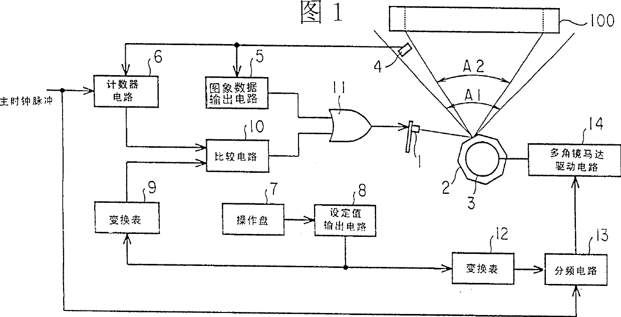
[0041] FIG. 1 is a diagram showing the configuration of main parts of a laser scanner according to a first embodiment of the present invention.

[0042] The laser scanner of this embodiment shown in the figure scans the photosensitive drum 100 with laser light, and exposes the photosensitive drum 100 by turning on and off the laser light. Moreover, this laser scanner has a laser diode 1, a polygon mirror 2 as an optical system of the deflection direction, a polygon mirror motor 3, a photodetector 4 as a laser detection device, an image output circuit 5 as a light emission control device, and a The counter circuit 6 of the device, the operation panel 7, the setting value output circuit 8, the conversion table 9 as the reference value output device and the reference value changing device, the comparison circuit 10 as the forced light em...


PUM


Abstract

A laser scanner is adapted to cause a laser beam to scan in the main-scanning direction by deflecting the laser beam by means of a deflecting optical system. A horizontal synchronizing signal is obtained by detecting the laser beam by means of a photodetector. Forced emission of laser beam is started after a predetermined time period since the detection of the laser beam, which predetermined time period is variable as a function of the rotary speed of the deflector section. With this arrangement, a horizontal synchronizing signal can be reliably detected if the rotary speed of the deflecting operation system fluctuates.

Description

[0001] Cross references to related applications [0002] This application is based on and has priority from prior Japanese Patent Application No. 2001-82611 filed on March 22, 2001, the entire contents of which are hereby incorporated by reference. technical field [0003] Field of the Invention The present invention relates to, for example, a laser scanner for performing exposure processing by laser light and a copier using the same, which are suitable for an electrophotographic image forming apparatus used as a recording portion of a digital copier. Background technique [0004] In the digital copying machine, based on the image data generated by reading the original document by the original document reading device, the image forming device prints on the paper to obtain a copy of the above original document. [0005] In this case, in order to obtain a copy similar to that of the original, the original reading device and the image forming device are respectively configured ...

Claims


Application Information

Patent Timeline
Patent Type & Authority Patents(China)
IPC IPC(8): B41J2/44B41J2/47G02B26/10H04N1/053H04N1/113H04N1/23
CPCH04N1/1135H04N2201/04755H04N1/053H04N2201/0471B41J2/471H04N2201/02439H04N2201/04732H04N2201/04744H04N2201/04794
Inventor 上野末男
Owner TOSHIBA TEC KK
Features
  • R&D
  • Intellectual Property
  • Life Sciences
  • Materials
  • Tech Scout
  • Unparalleled Data Quality
  • Higher Quality Content
  • 60% Fewer Hallucinations
Learn More