Supercharge Your Innovation With Domain-Expert AI Agents!

Ultrasonic probe and ultrasonic diagnostic device

A diagnostic device, ultrasonic technology, applied in ultrasonic/sonic/infrasonic diagnosis, ultrasonic diagnosis, infrasonic diagnosis, etc., can solve problems such as caliber limit and insufficiency

Active Publication Date: 2015-07-29
HITACHI HEALTHCARE MFG LTD
View PDF9 Cites 3 Cited by
  • Summary
  • Abstract
  • Description
  • Claims
  • Application Information

AI Technical Summary

Problems solved by technology

Therefore, there is also a limit to its caliber
On the other hand, when the channels are arranged in a two-dimensional matrix array, the number of channels to be processed in the ultrasonic probe may increase to the level of thousands of channels.
Therefore, the number of channels of the body beamformer is overwhelmingly insufficient for the number of channels of the probe

Method used


Image

  • Ultrasonic probe and ultrasonic diagnostic device
  • Ultrasonic probe and ultrasonic diagnostic device
  • Ultrasonic probe and ultrasonic diagnostic device

Examples


no. 1 example >

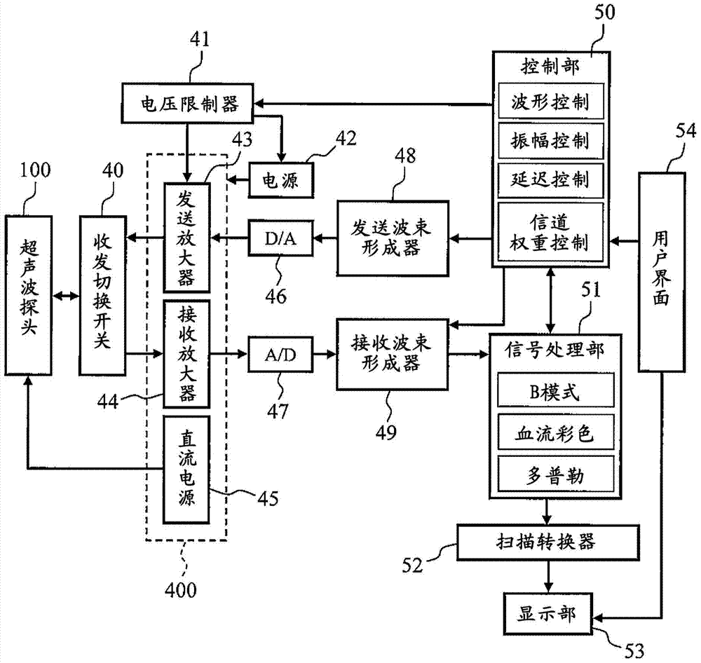
[0050] First, the device configuration of the ultrasonic diagnostic device and the signal flow before imaging will be described. image 3 The device configuration of a typical ultrasonic diagnostic device is shown.

[0051] The ultrasonic diagnostic device includes: an ultrasonic probe 100, a transceiving switch 40, a transmitting system and a receiving system circuit 400, a voltage limiter 41, a power supply 42, a DC power supply 45, a D / A converter 46, an A / D converter 47, and a transmitting beam The former 48 , the reception beamformer 49 , the control unit 50 , the signal processing unit 51 , the scan converter 52 , the display unit 53 and the user interface 54 . As will be described later, the DC power supply 45 is not required when connecting an ultrasonic probe that does not require a DC voltage.

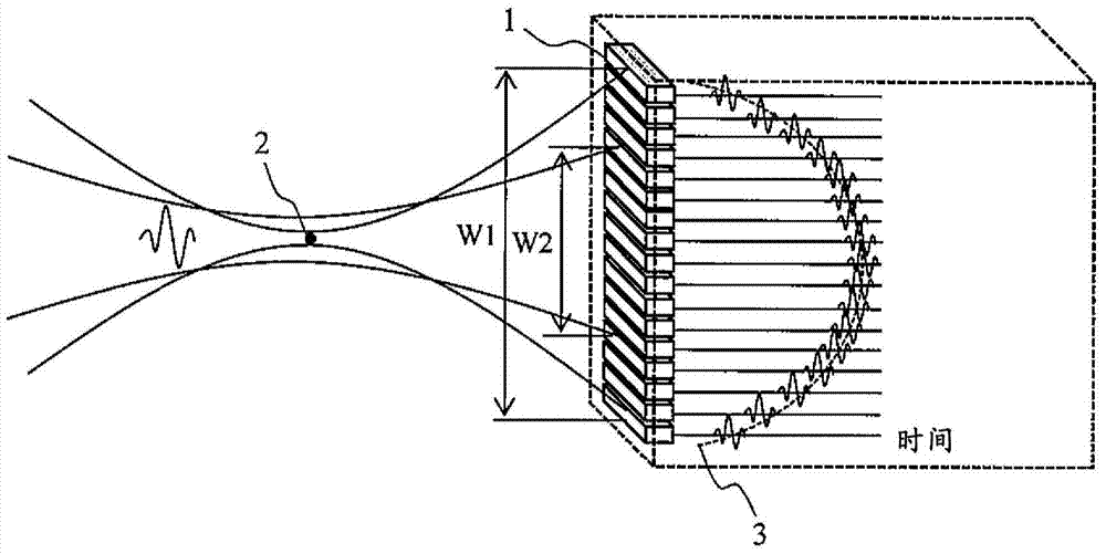
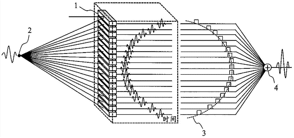
[0052] image 3 The Ultrasound Probe 100 with figure 1 and figure 2 The sonotrode 1 shown with a plurality of channels is comparable. Each channel of the ultrasonic pro...

no. 2 example >

[0094] In the first embodiment, the probe channels connected to the main beamformer are arranged consecutively near the center of the aperture, and the subarrays are arranged consecutively away from the aperture. However, when the performance difference between the main beamformer and the sub-beamformers is extremely large, there is a possibility that image quality may be adversely affected discontinuously when the aperture enters the sub-array region during imaging. Figure 15 A receiving system circuit in the ultrasonic diagnostic apparatus according to the second embodiment for solving such problems is shown. In addition, in Figure 15 Although the receiving system circuit is described as an example, the transmitting system circuit may have the same configuration.

[0095] exist Figure 15 The channels of the body beamformer 31 are divided into: a plurality of first body beamformer channels 32 and a plurality of second body beamformer channels 33 . Among the probe channe...

no. 3 example >

[0099] In the first and second embodiments described above, a one-dimensional array was assumed. However, the invention can also be applied to matrix arrays. Figure 16 This is a configuration example of a 1.25D or 1.5D array. 1.25D refers to a matrix array in which the short-axis aperture of the probe is variable, and 1.5D refers to a matrix array in which the focal point on the short-axis side can be arbitrarily set on the central axis of the short-axis aperture.

[0100] Figure 16 The array structure viewed from the acoustic radiation surface of the ultrasonic probe is shown. exist Figure 16 In the ultrasonic probe, the probe channel is divided not only in the direction of the long axis, but also in the direction of the short axis. The ultrasonic beam of 1.25D or 1.5D short-axis section is symmetrical to the center of the short-axis aperture, so the channels on both sides are usually short-circuited, or given the same delay time and weight.

[0101] In imaging, the a...


PUM


Abstract

This ultrasonic probe has a plurality of ultrasonic transducers, a given number of which constitute a single subarray, and is connected to a reception circuit that contains the following: at least one delay / addition circuit that performs a delay process and an addition process, by subarray, on received-ultrasound signals obtained from ultrasonic transducers in subarrays; and a second delay / addition circuit that performs a delay process and an addition process on received-ultrasound signals obtained from the ultrasonic transducers. The plurality of ultrasonic transducers comprise a first group and a second group. The received signals from the first group are sent to the second delay / addition circuit via the first delay / addition circuit(s), and the received signals from the second group are sent directly to the second delay / addition circuit without going through the first delay / addition circuit(s).

Description

technical field [0001] The present invention relates to the technology of an ultrasonic probe and an ultrasonic diagnostic device. Background technique [0002] An ultrasonic diagnostic apparatus is composed of a probe and an apparatus main body, and images the internal structure of a living body or the like using ultrasonic waves. An ultrasonic probe (probe) incorporates a plurality of ultrasonic vibrators (electroacoustic transducer elements), and transmits and receives ultrasonic signals. As the ultrasonic vibrator device, piezoelectric ceramics, single crystals, piezoelectric polymers, or capacitive transducers can be used. These devices generate ultrasonic waves by applying voltage and transmit the ultrasonic waves. Also, these devices generate electrical signals when they receive sound waves. [0003] Ultrasonic probes are usually arrayed by dividing transducers into numerous channels. At the time of imaging, an ultrasonic beam focused on a certain point is generat...

Claims


Application Information

Patent Timeline
Patent Type & Authority Applications(China)
IPC IPC(8): A61B8/00
CPCG01S15/8927G01S7/5208A61B8/4494A61B8/4488B06B1/0207B06B1/0622G10K11/346B06B2201/20B06B2201/76G01S15/8925A61B8/4444A61B8/5207A61B8/145
Inventor 田中宏树鳟泽裕
Owner HITACHI HEALTHCARE MFG LTD
Features
  • R&D
  • Intellectual Property
  • Life Sciences
  • Materials
  • Tech Scout
  • Unparalleled Data Quality
  • Higher Quality Content
  • 60% Fewer Hallucinations
Learn More