
Implanted pacemaker

A pacemaker and pacing technology, applied in cardiac stimulators, therapy, physical therapy, etc., can solve the problem of low energy consumption of the heart

Inactive Publication Date: 2006-01-11
MR3 MEDICAL LLC
View PDF10 Cites 3 Cited by
  • Summary
  • Abstract
  • Description
  • Claims
  • Application Information

AI Technical Summary

Problems solved by technology

However, these programs are not ideally designed to minimize the energy consumption of an already damaged patient's heart

Method used

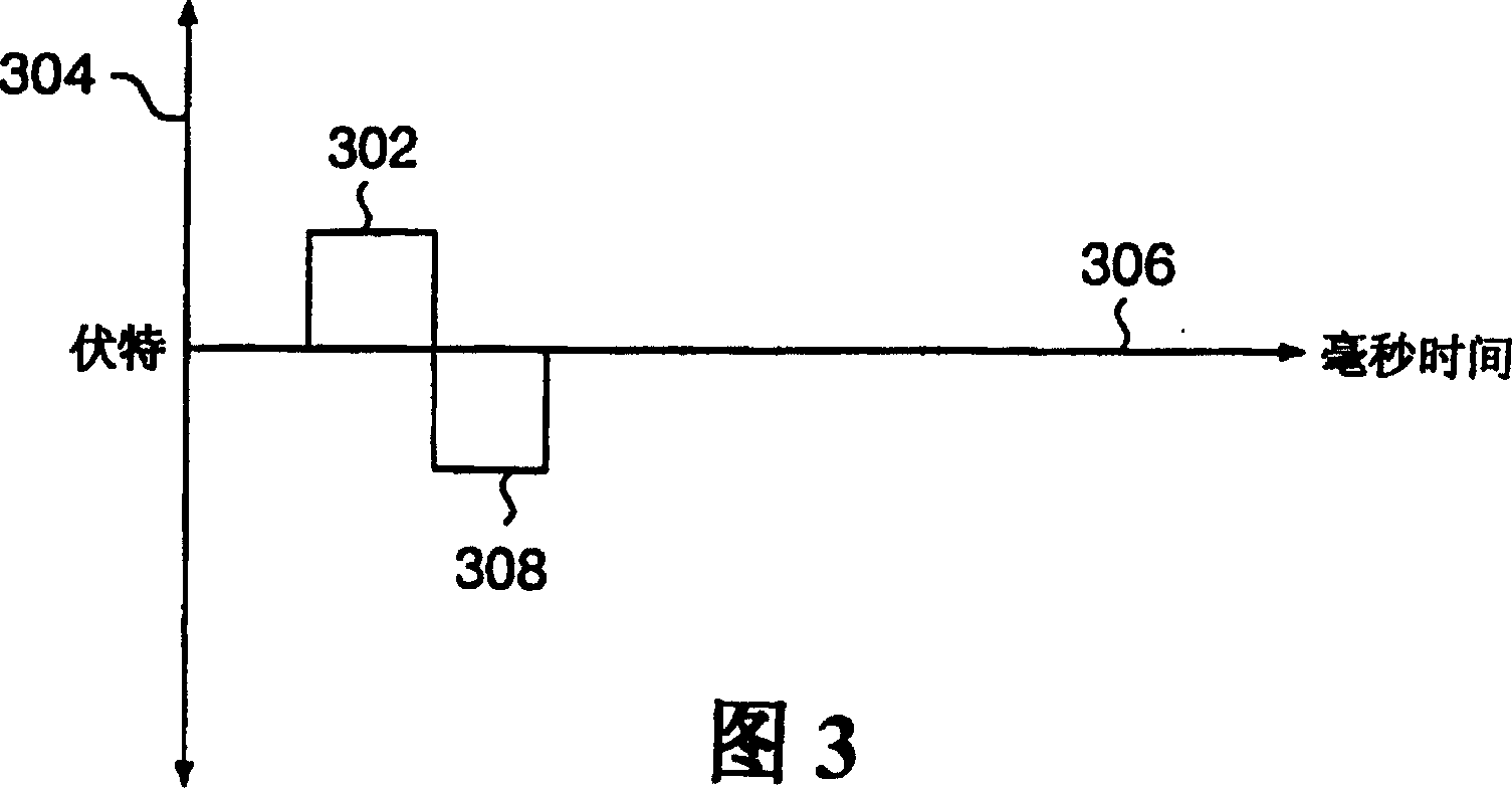

Image

  • Implanted pacemaker
  • Implanted pacemaker
  • Implanted pacemaker

Examples


Embodiment Construction

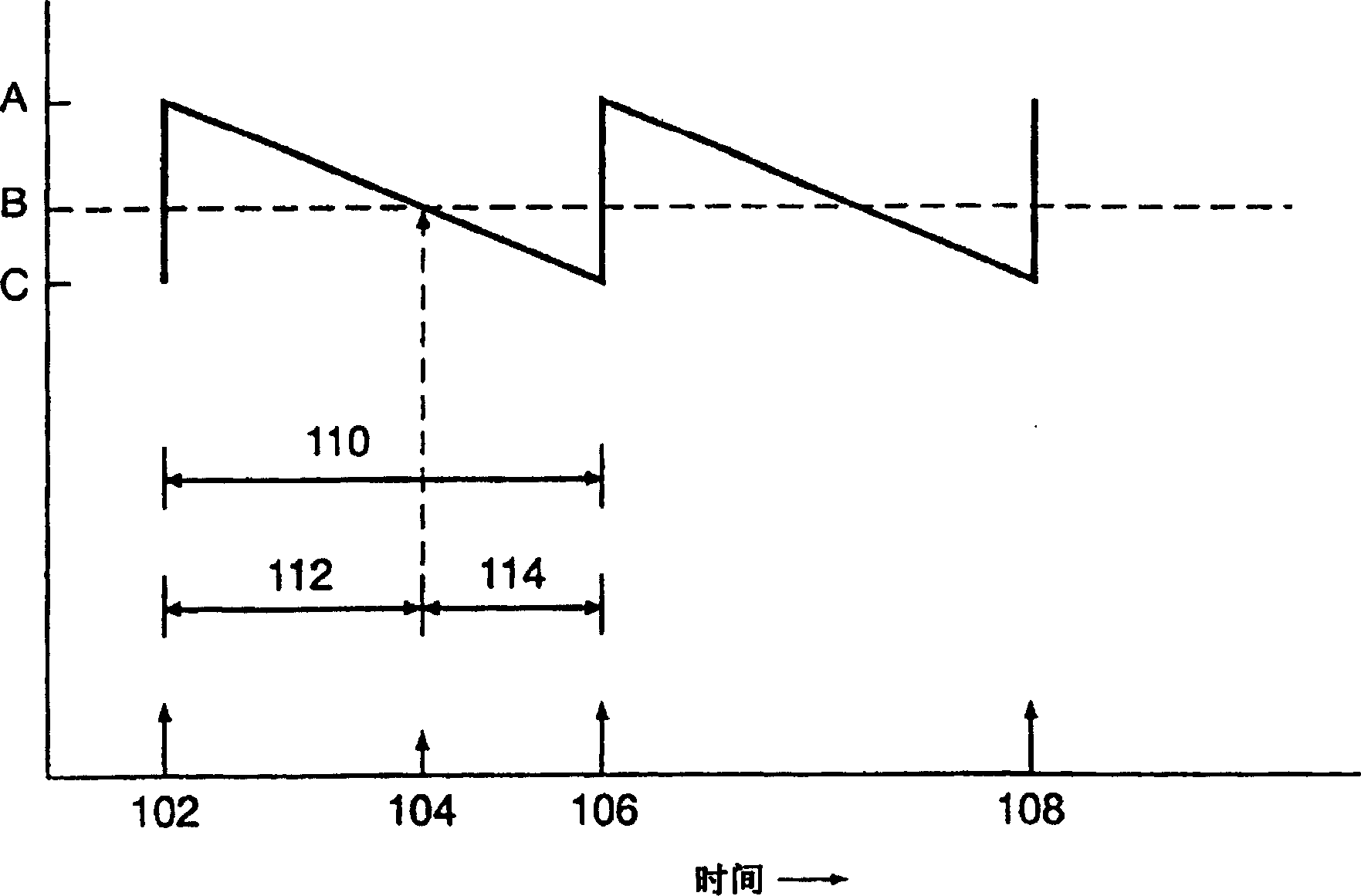
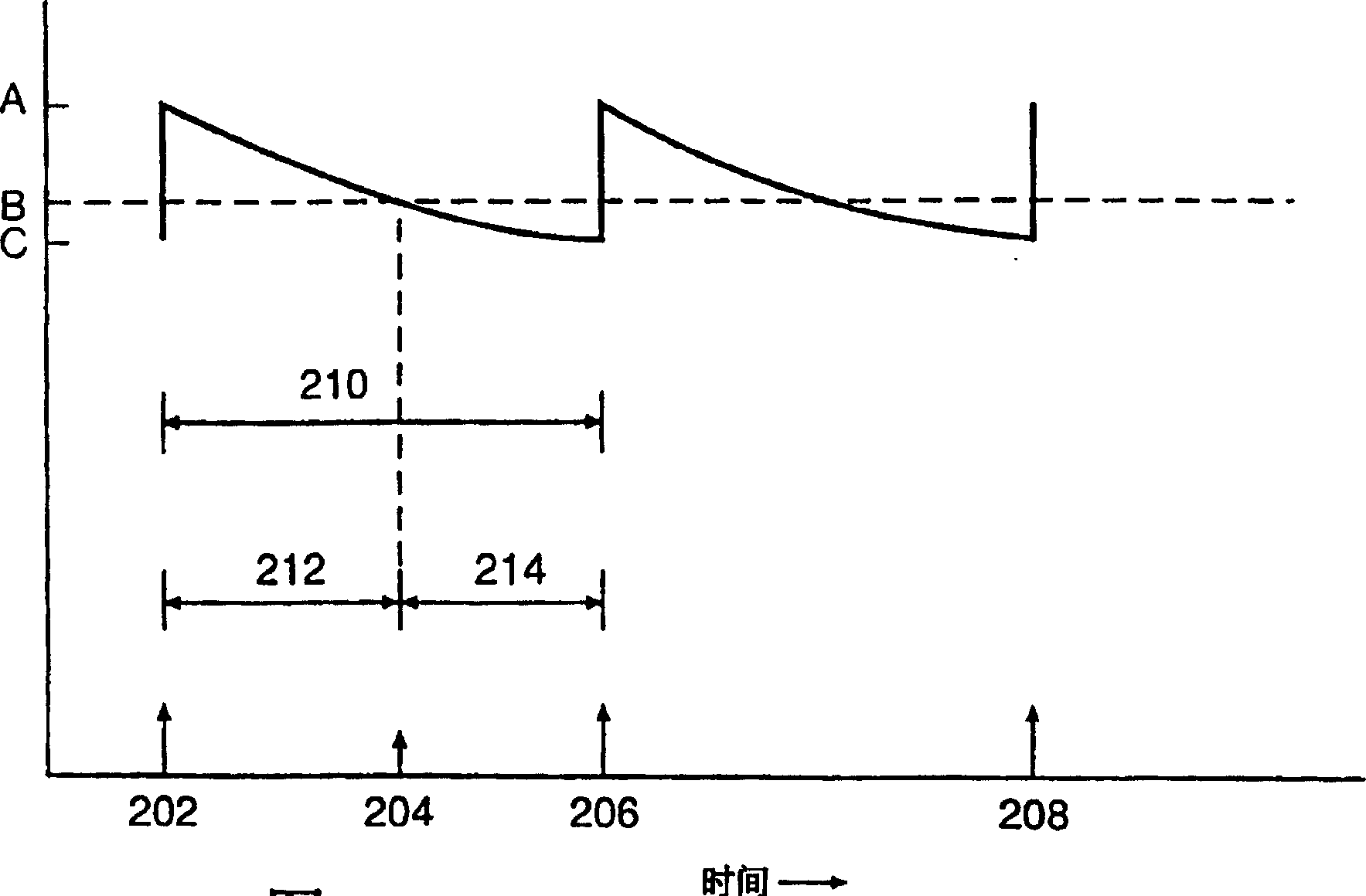
[0035] refer to figure 1 and figure 2 Can understand the principle of the present invention, figure 1 and 2 A cyclic stimulus-relaxation program of two ventricular pacing is depicted, in which the highest frequency of ventricular overdrive pacing is followed by relaxation to a frequency just below the intrinsic atrial trigger rate (corresponding to ventricular escape). figure 1 A cyclic sawtooth (linear decline) stimulus-relaxation profile for ventricular pacing is shown. figure 2 A cyclic exponentially decreasing stimulus-relaxation program for ventricular pacing is shown.

[0036] refer to figure 1 , showing a cyclic sawtooth stimulation-relaxation profile for ventricular pacing, with time points 102, 106, and 108 representing ventricular overdrive pacing with the highest pacing rate A, followed by a linear decline / relaxation to The pacing rate of the lowest pacing rate C. Each loop has a total duration 110. Intrinsic atrial trigger rate B is shown with a dotted ref...


PUM


Abstract

Method and apparatus for cyclic ventricular pacing starting at a rate just above the intrinsic atrial firing rate (overdrive pacing), followed by relaxation to a rate just below the intrinsic atrial firing rate (ventricular escape). The method and apparatus can be applied to one or both ventricles, and can utilize one or more electrodes per ventricle. The electrode(s) can be applied to inner or outer ventricular surfaces. Relaxation protocols as a function of time can be linear, curvilinear to include exponential, or mixtures thereof. Furthermore, relaxation protocols can include one or more periods of time during which the pacing rate is held constant. Typically, the average ventricular pacing rate using this invention will be slightly greater than the intrinsic atrial firing rate, though alternate embodiments that encompass average ventricular pacing rates that are equal to or slightly less than the intrinsic atrial firing rate are also envisioned. Application of this method and apparatus to a heart in need thereof will produce a heart with an optimally minimized energy output requirement.

Description

technical field [0001] The present invention generally relates to a pacemaker for controlling the heartbeat. More specifically, the present invention relates to a pacemaker for overdriving the ventricles by triggering at an average frequency slightly greater than the intrinsic (atrial) rate, cyclically promoting ventricular tracking of atrial pacing, and then gradually slowing down the ventricular stimulation To the point where ventricular beating is disconnected from atrial triggering, especially in combination with ventricular synchronization techniques such as biventricular pacing, biphasic, and / or multiple site ventricular pacing. Background technique [0002] AV block, common in cardiac patients, occurs when electrical impulses traveling along the conduction tract from the sinoatrial node are delayed in reaching the atrioventricular junction / node. In some cases, if the AV delay is long enough, the ventricles will beat at their inherently slower ventricular rhythm. In ...

Claims


Application Information

Patent Timeline
Patent Type & Authority Patents(China)
IPC IPC(8): A61N1/368A61N1/36A61N1/362A61N1/365A61N1/37
CPCA61N1/36514A61N1/3622A61N1/36592A61N1/368A61N1/3712A61N1/365
Inventor 莫顿·M·莫厄尔
Owner MR3 MEDICAL LLC
Learn More