Supercharge Your Innovation With Domain-Expert AI Agents!

Medical valve with positive flow characteristics

A valve and the first fluid technology, applied in other medical devices, valves, flow control, etc., can solve problems such as blocked passages and difficulties, and achieve the effects of avoiding negative flow, easy production and use, and avoiding blood clogging

Inactive Publication Date: 2006-01-18
ICU MEDICAL INC
View PDF0 Cites 0 Cited by
  • Summary
  • Abstract
  • Description
  • Claims
  • Application Information

AI Technical Summary

Problems solved by technology

Because of the small channel space of these catheters, even a small amount of suction will draw a sufficient amount of blood through the catheter back to the valve so that the blood is drawn into the tip of the catheter where it may block the passage
[0010] It is more difficult to overcome the above problems when considering other aspects of the standard that the valve must meet

Method used


Image

  • Medical valve with positive flow characteristics
  • Medical valve with positive flow characteristics
  • Medical valve with positive flow characteristics

Examples


Embodiment Construction

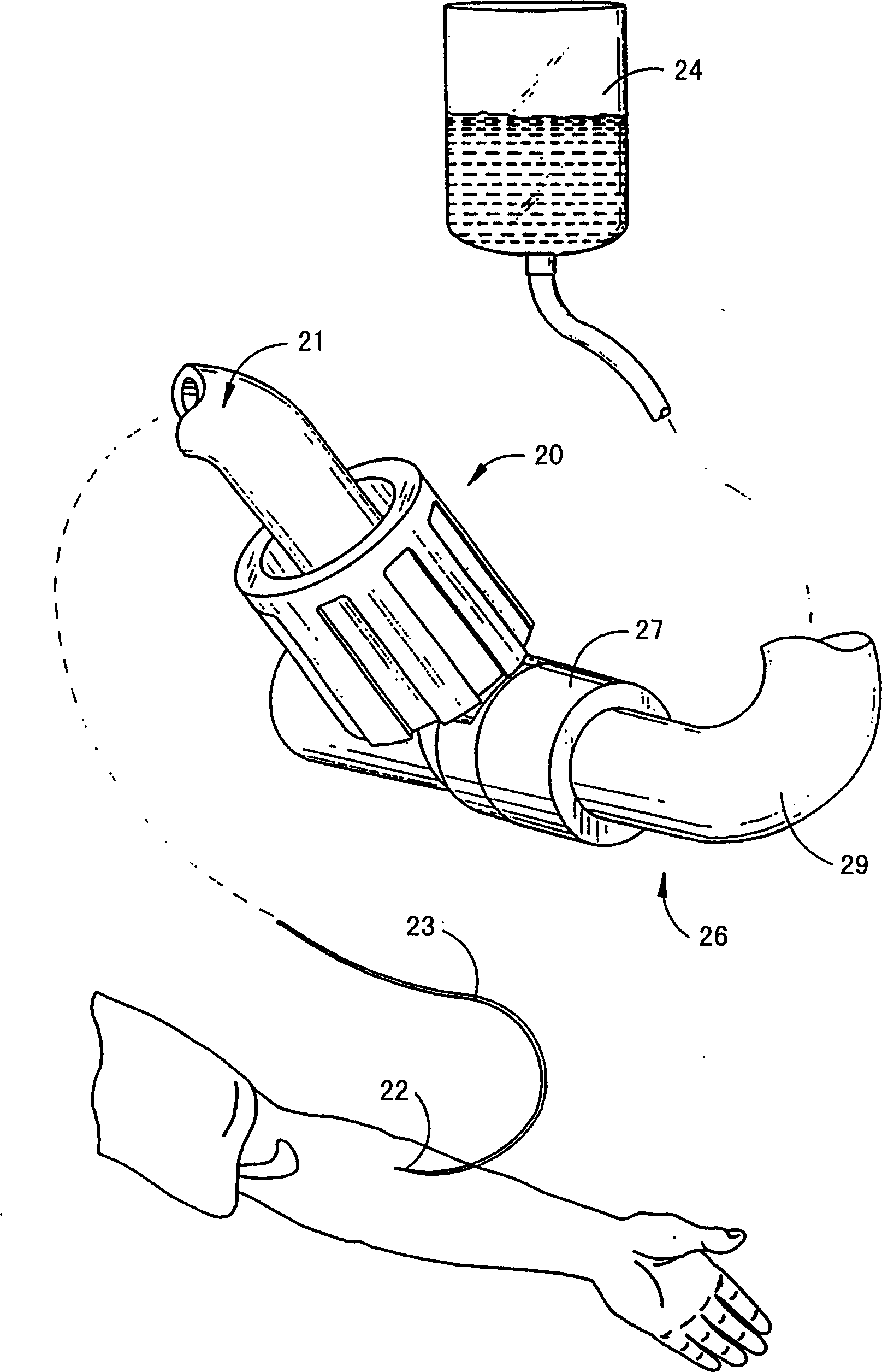
[0078] Figure 1-17 A valve 20 according to a first embodiment of the invention is shown. figure 1 A specific application that is very suitable for the valve 20 is shown. Of course, the valve 20 can also be applied to many other occasions.

[0079] Such as figure 1 As shown in the figure, the valve 20 is preferably selected to control the flow of fluid to the conduit 22 from a fluid source 24 such as an I.V. bag. In this structure, the first medical device 21 is connected to the valve 20. The first medical device 21 contains a pipeline 23 leading to a catheter 22. The pipe 23 is connected to the valve 20 at one end, and the tip of the catheter 22 is located in the patient's body.

[0080] The second medical device 26 is also connected to the valve 20. The second medical device 26 includes a connector 27 at one end of a tube 29 leading to the I.V. bag 24.

[0081] When so connected, the valve 20 allows fluid to flow from the I.V. bag 24 or other source of medical fluid to the ca...


PUM


Abstract

A medical valve device for use in selectively establishing a fluid flow between first and second medical implements is disclosed. The valve has a body defining a passage from a first port to a second port. The valve defines a first fluid volume when both medical implements are connected thereto, and a second, smaller volume when one of the implements is disconnected, thereby causing a positive flow of fluid from the valve to the second medical implement when the first implement is disconnected.

Description

Technical field [0001] The present invention generally relates to a medical valve, and more specifically to a valve that, when connected between a first medical device such as a fluid source and a second medical device such as a catheter, facilitates the flow of fluid therebetween, And when the first medical device is disconnected, a positive flow of fluid in the direction of the second medical device can be generated through the valve. Background technique [0002] Connectors and valves are usually used in the treatment of parenteral therapy in hospitals and in medical settings to selectively allow fluid to flow between two points. These valves are usually placed on the fluid flow path leading to the patient or other destinations. For example, the tubing can lead to a catheter with the tip of the catheter located in the patient's body. [0003] By setting the valve in this way, a fluid source or other pipelines can be connected to it for supplying fluid from the fluid source to ...

Claims


Application Information

Patent Timeline
Patent Type & Authority Patents(China)
IPC IPC(8): A61M39/26A61M39/00A61M5/168A61M39/04
CPCA61M39/26A61M39/045A61M2039/263A61M2039/266
Inventor 托马斯·F·方古若乔纳森·T·施密特丹尼尔·J·维特丹尼斯·M·布伊
Owner ICU MEDICAL INC
Features
  • R&D
  • Intellectual Property
  • Life Sciences
  • Materials
  • Tech Scout
  • Unparalleled Data Quality
  • Higher Quality Content
  • 60% Fewer Hallucinations
Learn More