Rolling mill with laterally different velocities

A technology of rolling mills and rolls, applied in the field of transverse differential rolling mills, which can solve the problems of different or uneven distribution in the transverse direction, thinning of edges, convexity of rolled pieces, etc.

Inactive Publication Date: 2006-02-15
IHI CORP
View PDF0 Cites 0 Cited by
  • Summary
  • Abstract
  • Description
  • Claims
  • Application Information

AI Technical Summary

Problems solved by technology

The object of the present invention is to provide a transverse differential rolling mill which can apply rolling force to workpieces with different or non-uniform distribution laterally, and which can quickly adjust the distribution curve during the rolling process. Therefore, compared with the traditional differential rolling mill , it basically solves the problem of edge thinning and rolled piece crown

Method used


Image

  • Rolling mill with laterally different velocities
  • Rolling mill with laterally different velocities
  • Rolling mill with laterally different velocities

Examples


Embodiment Construction

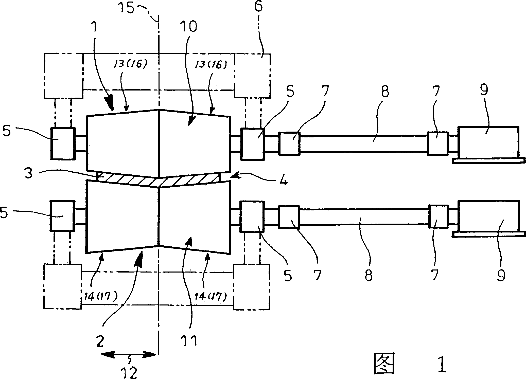
[0066] 1-6 show a first embodiment of the transverse differential rolling mill of the present invention. As shown in FIG. 1, a pair of upper roll 1 and lower roll 2 for rolling a workpiece 3 are rotatably supported by roll chocks 5 in a stand 6 at their roll ends. The rollers 1 and 2 are connected at one end (the right end of FIG. 1 ) to an independent rotary drive mechanism 9 through a universal joint 7 and a drive shaft 8, so that the speed ratio of the rollers 1 and 2 can be changed as required.

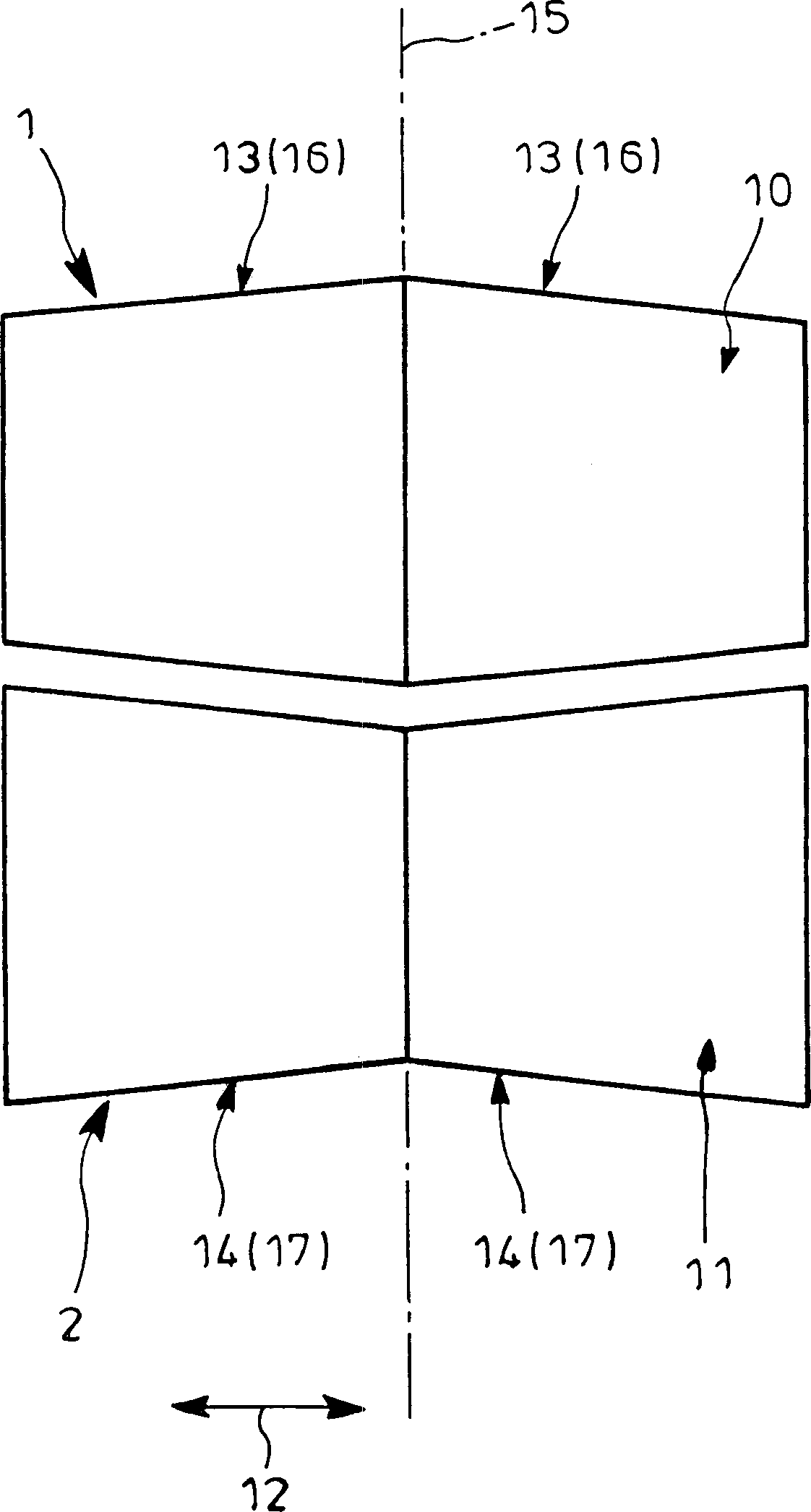
[0067] Such as figure 2 As shown in enlargement, the roll bodies 10, 11 of the rolls 1, 2 respectively include roll segments 13, 14 with different diameters and shape changes along the roll axis 12, so that the roll diameters of the roll segments 13, 14 of the roll bodies 10, 11 and are substantially constant and each roller 1, 2 is left-right symmetrical. Specifically, in this embodiment, the roll body 10 includes an outwardly converging roll section 16 that has a maximum diam...


PUM


Abstract

Each of a pair of rolls has a barrel with different diameters axially of the barrel such that sum of the diameters of the barrels is substantially constant and that each of the rolls is bilaterally symmetrical. The rolls themselves have an ability to control workpiece profile.

Description

technical field [0001] The invention relates to a transverse differential rolling mill. Background technique [0002] Typically, metal workpieces are rolled by passing between upper and lower rolls in a rolling mill. [0003] It is known in the art that during rolling, such as Figure 28 As shown, rotating the upper roll 1 and the lower roll 2 with different rotational speeds or different peripheral speeds will cause the reverse frictional shear force to act on the upper and lower surfaces of the rolled piece 3 passing through the roll gap 4; Compared with the rolling operation performed by rotating the rolls 1 and 2 at the same speed, the same rolling reduction is obtained at a lower rolling force, or a higher rolling reduction is obtained at the same rolling force The amount of depression. This is known as circumferential differential rolling or differential rolling, and such rolling techniques are widely used. [0004] In the above-mentioned differential rolling, the g...

Claims


Application Information

Patent Timeline
Patent Type & Authority Patents(China)
IPC IPC(8): B21B1/22B21B37/34B21B13/02B21B13/14B21B27/02B21B27/05
CPCB21B2013/025B21B27/05B21B37/34B21B13/02B21B2267/065B21B2027/022B21B1/222B21B2275/05B21B13/14
Inventor 三上昌夫口诚宽新谷定彦岩崎孝行西井崇
Owner IHI CORP
Why Eureka
Try Eureka