Roll stand for hot-rolling or cold-rolling metallic strips

A technology of rolling mill stand and metal strip, applied in the direction of metal rolling stand, metal rolling mill stand, metal rolling, etc., can solve the problem that residual gap cannot be eliminated by this, and achieve the effect of sensitive movement

Inactive Publication Date: 2006-03-15
SMS DEMAG AG
View PDF2 Cites 1 Cited by
  • Summary
  • Abstract
  • Description
  • Claims
  • Application Information

AI Technical Summary

Problems solved by technology

However, in this way, a large guide surface is provided,

Method used


Image

  • Roll stand for hot-rolling or cold-rolling metallic strips
  • Roll stand for hot-rolling or cold-rolling metallic strips
  • Roll stand for hot-rolling or cold-rolling metallic strips

Examples


Embodiment Construction

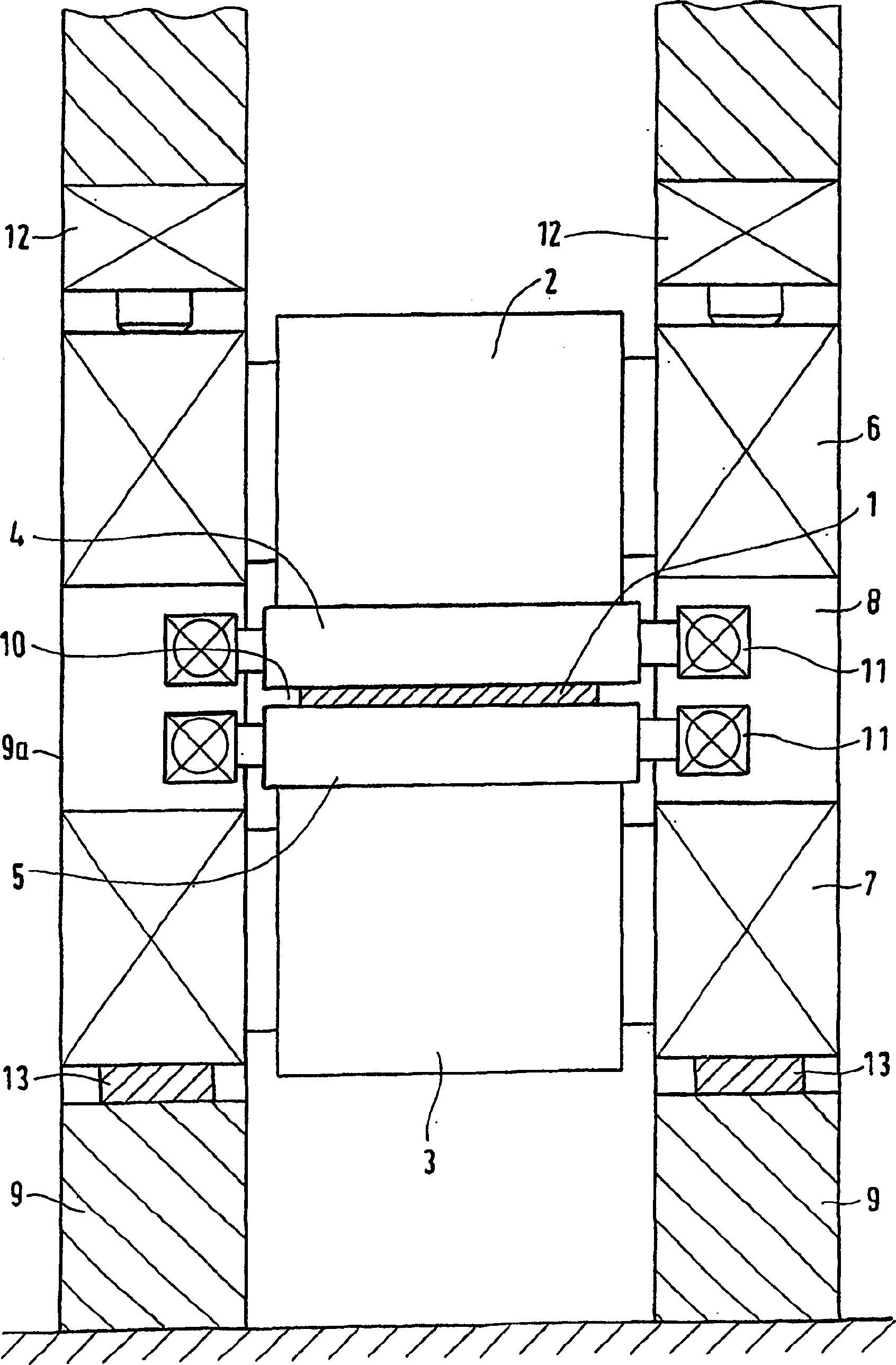
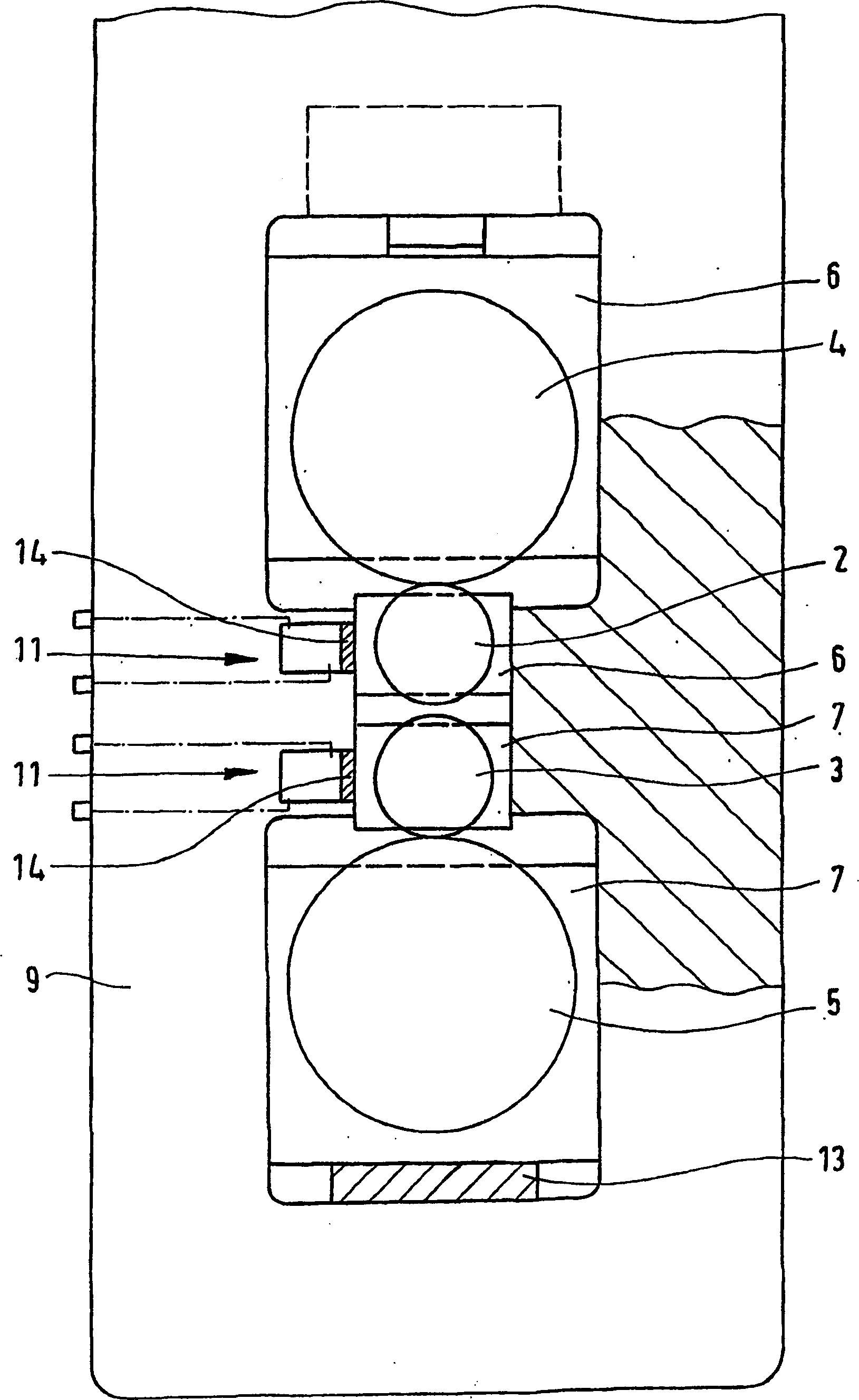
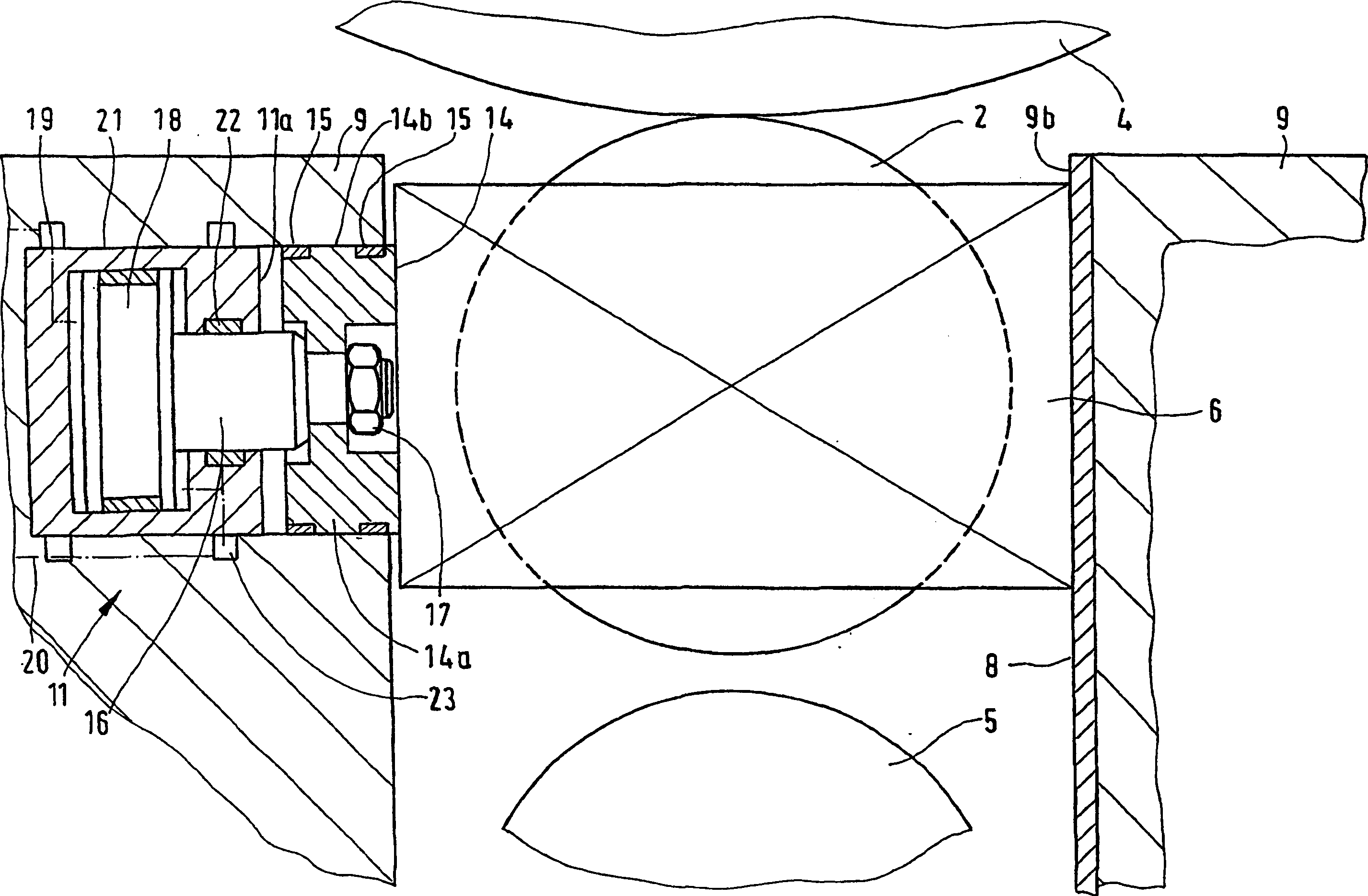
[0032] according to figure 1 The rolling mill stand is a four-high rolling mill stand for hot-rolling or cold-rolling metal strip 1 such as various steel strips, which has backup rolls 2, 3 and work rolls 4, 5, which are rotatably supported on roll stands 6 , 7 miles. The roll stands 6 , 7 for the support rolls 2 , 3 or for the work rolls 4 , 5 are guided on both sides in the guide rails 8 of the frame housing 9 in order to adjust the roll gap 10 . Furthermore, in the frame archway 9, a horizontal piston-cylinder unit 11 is provided at least on one side for the work rolls 4, 5 in order to adjust the gap between the roll seats 6, 7 (see figure 2 ).

[0033] The upper back-up roll 2 is equipped with servo hydraulic cylinders 12, which perform AGC accordingly. The lower roller base 7 stands still on the pressure measuring head 13 of the frame archway 9 . When the vertical roll-pressing drive mechanism stops working, the work roll stands 6, 7 of at least one frame side 9a are...


PUM


Abstract

The invention relates to a roll stand for hot-rolling or cold-rolling metallic strips. Said roll stand comprises back-up rolls and work rolls (2,3; 4,5) which are respectively positioned in chocks (6; 7) in a rotating manner. Each chock (6; 7) can be displaced on two sides in guiding devices (8) of the column frame (9) for adjusting the roll gap (10) and can be additionally displaced on at least one side for adjusting the play, by means of horizontal piston cylinder units (11) arranged in the column frame (9). The aim of the invention is to completely eliminate the play in the vertical guiding device (8) of the work roll chocks (6; 7) during the rolling. To this end, the chocks which are guided on at least one side of the column (9a) by means of the piston cylinder unit (11) arranged in the column frame (9) and by means of one respective support element (14) which is arranged on the front side of the piston (11a), can be pressed against the other side of the column (9b) and the guiding device (8) thereof without play when the vertical roll positioning drive is stopped, and can be released when the vertical roll positioning drive is switched on.

Description

technical field [0001] The present invention relates to a rolling mill stand for hot or cold rolling of metal strips, such as various steel strips, which has backup rolls and work rolls, which are rotatably supported in roll stands, wherein these roll stands can be positioned on two sides, respectively. The sides are adjusted in the guide rails of the frame arch to adjust the roll gap and they can also be adjusted at least on one side to adjust the gap by means of a horizontal piston-cylinder unit arranged in the frame arch. Background technique [0002] Work rolls in strip mills are replaced every 4 to 6 hours due to wear. At present, the work roll changing operation is carried out according to an automatic cycle by means of a roll changing device. In order to obtain a free roll seat gap when vertically pressing to control the roll gap, a gap of a few millimeters is specified between the machine frame and the roll seat. This gap is not good for rolling. [0003] When hot...

Claims


Application Information

Patent Timeline
IPC IPC(8): B21B31/02B21B31/20B21B31/18B21B31/00B21B29/00B21B31/32
CPCB21B31/02B21B29/00B21B31/18B21B31/32B21B2031/206B21B31/203
Inventor D·费格
Owner SMS DEMAG AG
Why Eureka
Try Eureka