
Transfer pump for block and stem material

A technology for conveying pumps and materials, which is applied in the field of conveying equipment for tuber materials. It can solve problems such as material damage, low production efficiency, and waste of raw materials, so as to reduce radial and tangential impact forces, avoid cutting and crushing impacts, The effect of active fraction growth

Inactive Publication Date: 2006-04-12
东台市食品机械厂有限公司
View PDF0 Cites 0 Cited by
  • Summary
  • Abstract
  • Description
  • Claims
  • Application Information

AI Technical Summary

Problems solved by technology

At present, most of the cutting (slicing) processing and transportation of tuber materials (such as potatoes, etc.) adopt mechanical methods. This type of processing method not only has low yield and poor appearance quality, but also has high labor intensity and low production efficiency. Difficult to adapt to the growing market demand for potato products
For this reason, there has been a method of using a pump as a power source for material delivery, and by means of hydraulic power to directly transport the material and push it to the cutting tool to complete the cutting and processing of the tuber material. The common impeller pump with multiple blades is still used. After the tuber material enters the impeller channel formed by the front and rear blades with the water flow, due to the different density of the transported material and the water flow, the material that follows the front blade into the impeller channel quickly. It is damaged by the impact of the blade surface of the rear blade. When this impact occurs at the outlet of the rear blade, the outlet end of the blade will cut and crush the material, causing a large amount of damage to the material, resulting in waste of raw materials and a decrease in the yield , in severe cases, the whole machine will not work normally

Method used


Image

  • Transfer pump for block and stem material
  • Transfer pump for block and stem material
  • Transfer pump for block and stem material

Examples


Embodiment Construction

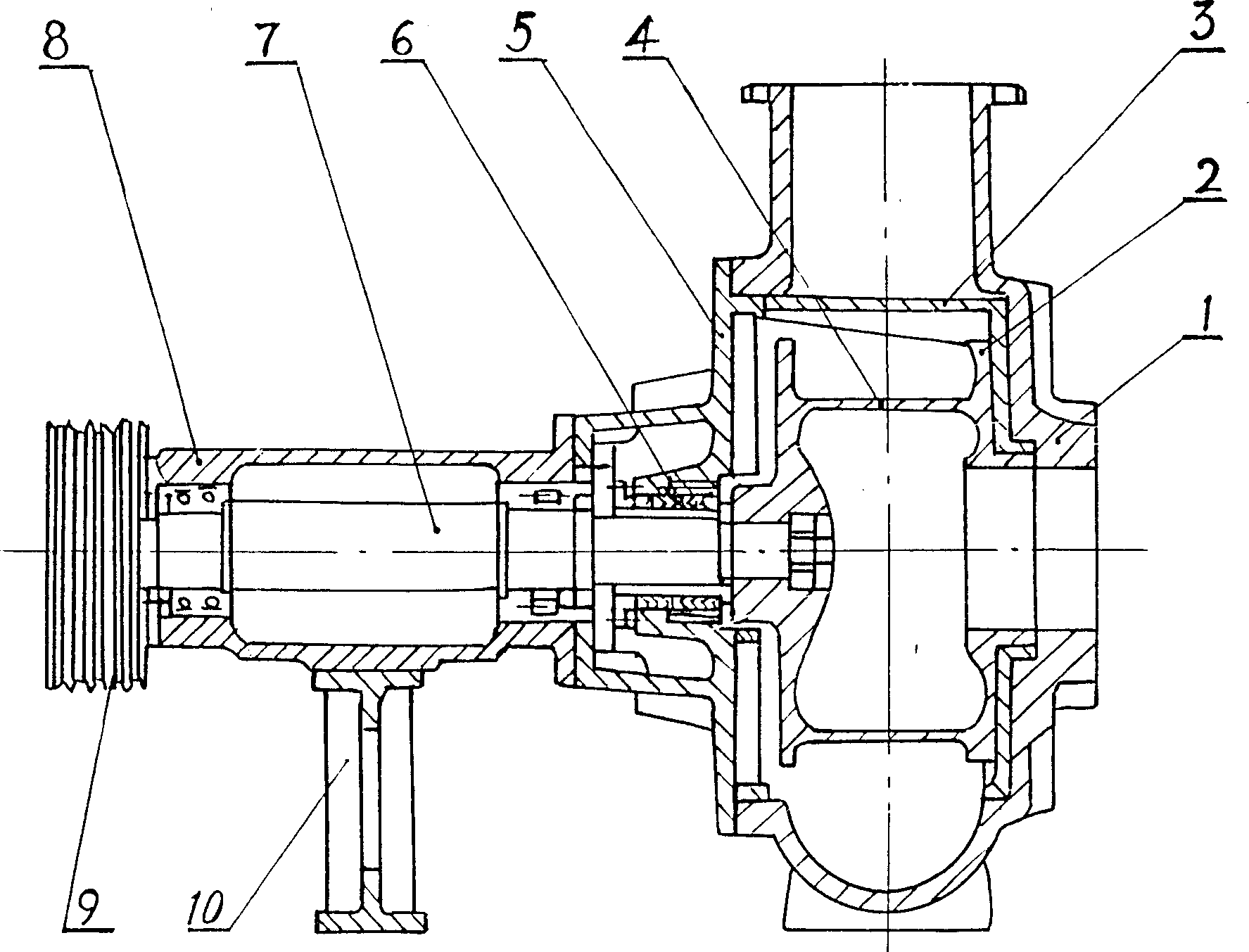
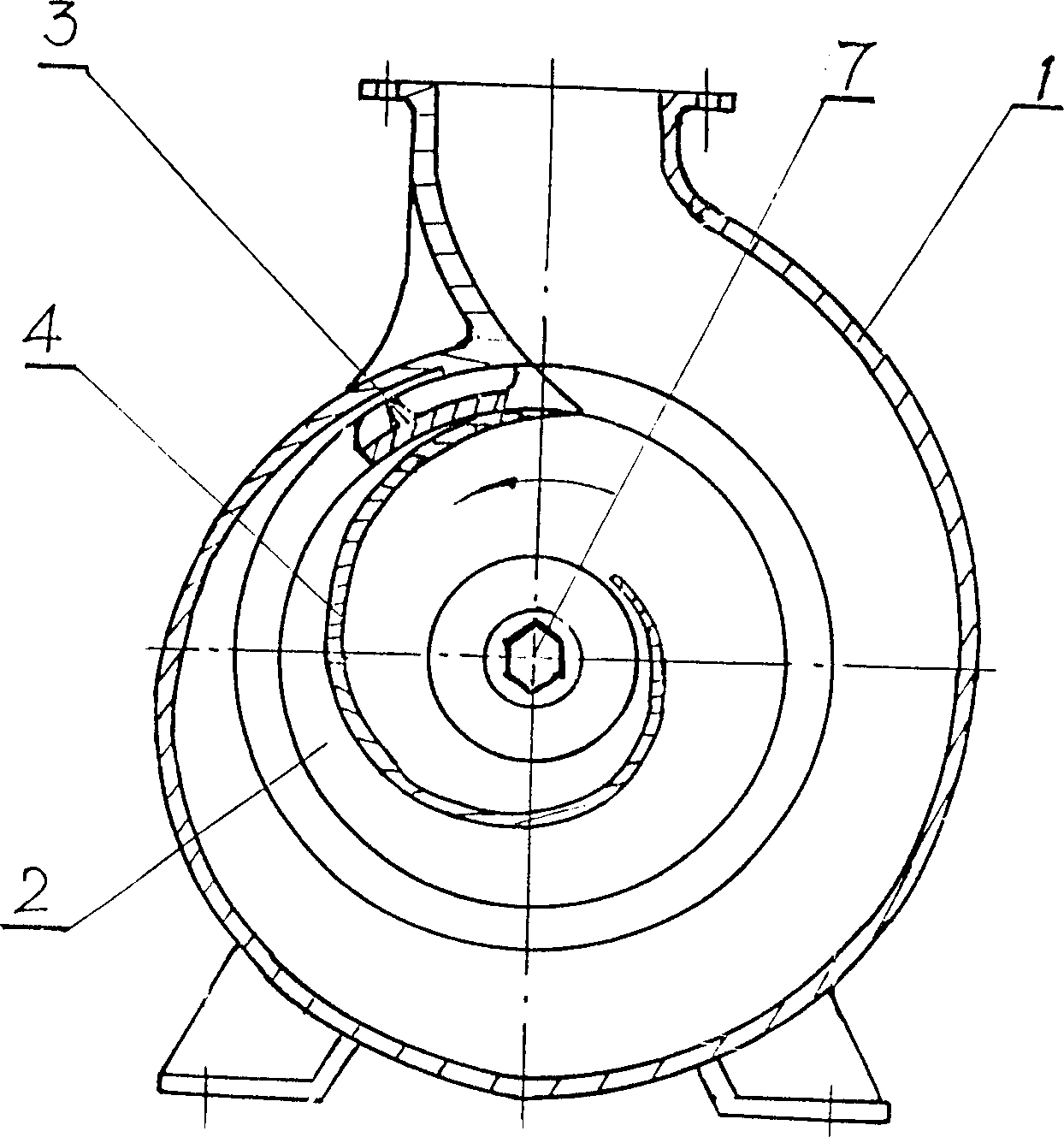
[0013] figure 1 , figure 2 Shown is a tuber material delivery pump of the present invention, the feed hole on the pump body 1 corresponds to the position of the impeller feed inlet of the impeller 2, and the flow channel of the pump body 1 is an involute variable-section flow channel; it is fixedly installed on The partition tongue 3 on the pump body 1 is located above the impeller 2, and a detachable structure is adopted between the partition tongue 3 and the pump body 1, which not only helps to improve the processing accuracy and manufacturability of the partition tongue, but also prevents the return of materials and reduces Water leaks back, which is beneficial to improve the working efficiency of the pump. The impeller drive shaft 7 is supported on the bearing bracket 8 through bearings, and extends into the pump body 1 through the pump cover 5, and the impeller 2 is installed at the front end of the impeller drive shaft 7; the above-mentioned bearings adopt roller beari...


PUM


Abstract

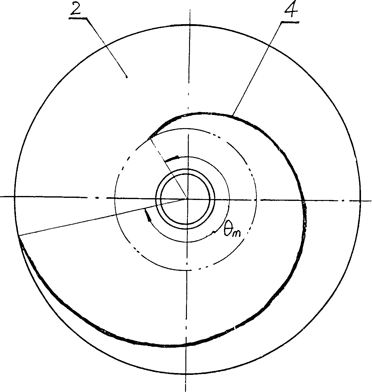
The invention discloses a tuber material transfer pump which comprises a pump body and an impeller driving shaft mounted on the pump body, an impeller is mounted on the impeller driving shaft, the impeller has only one blade with a helical form cross section and a wrap angle equal or greater than 225 degree. The invention can be applied in the transfer of tuber material e.g. potato, fruits and vegetables with high transfer efficiency and no damage to the material.

Description

Technical field [0001] The invention belongs to the technical field of food processing, and in particular relates to conveying equipment for tuber materials such as potatoes, fruits and vegetables. Background technique [0002] my country is rich in tuber resources such as potatoes, fruits and vegetables, and its finished products, especially French fries and potato chips made from potatoes, are one of the foods that consumers like very much. At present, most of the cutting (slicing) processing and transportation of tuber materials (such as potatoes, etc.) adopt mechanical methods. This type of processing method not only has low yield and poor appearance quality, but also has high labor intensity and low production efficiency. Difficult to adapt to the growing market demand for potato products. For this reason, there has been a method of using a pump as a power source for material transportation, and by means of hydraulic power to directly transport the material and push it...

Claims


Application Information

Patent Timeline
Patent Type & Authority Patents(China)
IPC IPC(8): F04D29/24F04D13/02
Inventor 何贤用张曙秋
Owner 东台市食品机械厂有限公司
Learn More