Improved reverberatory screen for radiant burner
A reflective screen and radiation furnace technology, applied in the direction of burner, combustion type, combustion method, etc., can solve the problem of limiting the working temperature of radiation type combustion furnace
- Summary
- Abstract
- Description
- Claims
- Application Information
AI Technical Summary
Problems solved by technology
Method used
Image

Examples
example 1
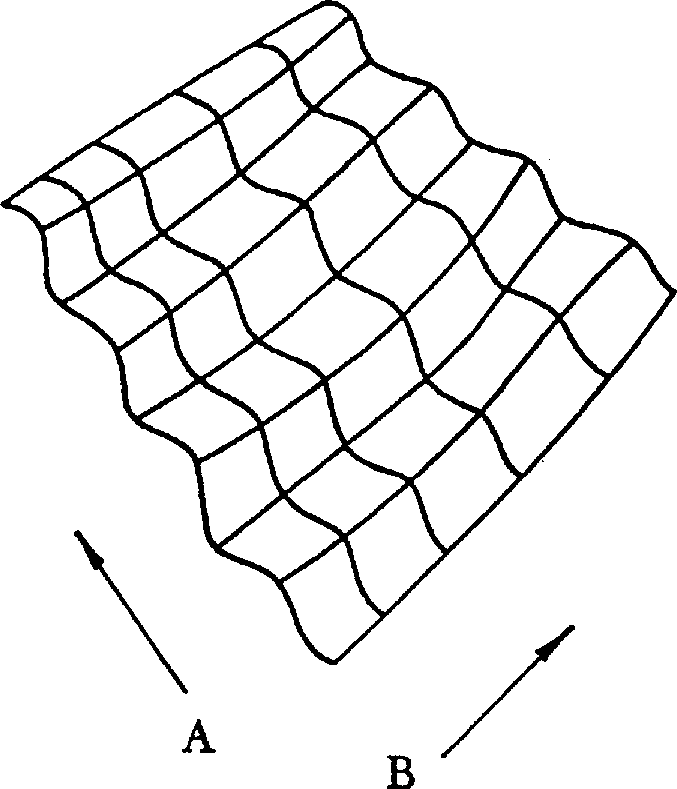
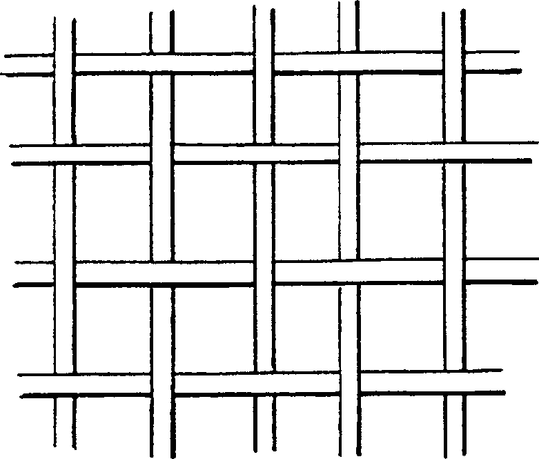
[0062] Silicon carbide fiber bundle (the diameter of single fiber is 15-20 micron, and the fineness is the Nicalon of 1800 deniers, produced by Nippon Carbon Co., Ltd. in Tokyo, Japan) is woven into a porous simple braid, with 1.8 per centimeter root fiber bundles. This fabric has an open area of approximately 50%. The fabric was then impregnated with a mixture of polymethyl methacrylate resin and boron carbide particulate antioxidant (average particle size 2-3 microns) as described in the Gray patent. The impregnated porous fabric was then formed into corrugated shapes in graphite molds. These folds are about 1 cm high and about 1 cm wide.
[0063] The molded screen was placed into a low pressure chemical gas permeation reactor having a deposition chamber about 1.4 meters in diameter and about 2 meters in length. Methane is fed into the reactor at a flow rate of approximately 15 standard liters per minute (Slpm), at low pressure (less than 100 Torr) and at a temperature ...
example 2
[0067] A reflective screen having a width of about 2 cm using fewer corrugations, ie wider corrugations, can be produced in exactly the same way as described in Example 1. Then conduct a comprehensive test of radiation output and heat engine on the finished screen. It was determined that the radiant output of the furnace with the reflective screen was 33% higher than that of the furnace without the screen. The two percent reduction in radiant output compared to a reflective screen with more corrugations (such as that of Example 1) is due to the smaller effective surface area for radiation.
[0068] The same screen was thermally cycled exactly as described in Example 1. After about 4000 switches, no changes were observed on the screen and the test was stopped.
example 3
[0070] The screen described in Example 1 was made from the same Nicalon(R) fiber, but the acrylic resin was replaced with phenolic resin (designation SC-1008, Borden, Ohio). The purpose of the phenolic resin is to harden the fiber into a corrugated shape in the mold during the plasticization process, and at the same time form a carbonaceous interface on the surface of the fiber. Thus, a CVI reactor is not used to deposit a separate layer of carbon. Instead, the above molded screen using phenolic resin is heated to about 1000°C in an inert gas atmosphere, which converts the resin into glassy carbon. The screen was removed from the mold and placed into a SiC CVI reactor as described in Example 1. Upon cooling, the finished screen can be seen to harden and become a self-supporting part.
PUM
 Abstract
Description
Claims
Application Information
 - R&D Engineer
- R&D Manager
- IP Professional
- Industry Leading Data Capabilities
- Powerful AI technology
- Patent DNA Extraction
Browse by: Latest US Patents, China's latest patents, Technical Efficacy Thesaurus, Application Domain, Technology Topic.
© 2024 PatSnap. All rights reserved.Legal|Privacy policy|Modern Slavery Act Transparency Statement|Sitemap