Ceramic composite material for optical conversion and use thereof

a composite material and optical conversion technology, applied in the direction of basic electric elements, chemistry apparatus and processes, and compositions of light-emitting components, can solve the problems of high cost, high cost, and high cost, and achieve the effect of improving the heat resistance and ultraviolet light resistance of resins for coating layers and molded layers, and achieving good reproducibility

Active Publication Date: 2006-06-15
UBE IND LTD
View PDF7 Cites 57 Cited by
  • Summary
  • Abstract
  • Description
  • Claims
  • Application Information

AI Technical Summary

Benefits of technology

[0008] The present inventors have found that the above-described object can be attained by a solidified body comprising two or more oxides an

Problems solved by technology

However, according to this method, uniform white light can be hardly obtained with good reproducibility because of difficulty in control for, for example, ensuring uniform mixing of the phosphor powder and the resin, or optimizing the thickness of coated film.
Also, use of a phosphor powder having low transparenc

Method used


Image

  • Ceramic composite material for optical conversion and use thereof
  • Ceramic composite material for optical conversion and use thereof
  • Ceramic composite material for optical conversion and use thereof

Examples


example 1

[0058] An α-Al2O3 powder (purity: 99.99%) and a Y2O3 powder (purity: 99.999%) were mixed at a ratio of 82:18 by mol and a CeO2 powder (purity: 99.99%) was mixed to have a ratio of 0.01 mol per mol of Y3Al5O12 produced by the reaction of oxides charged. These powders were wet-mixed in ethanol by a ball mill for 16 hours and, then, the ethanol was removed by using an evaporator to obtain a raw material powder. This raw material powder was preliminarily melted in a vacuum furnace and used as a raw material for the unidirectional solidification.

[0059] The obtained raw material was charged into a molybdenum crucible and, then the crucible was set in a unidirectional solidification apparatus. The raw material was melted under a pressure of 1.33×10⁻³ Pa (10−5 Torr). In the same atmosphere, the crucible was moved down at a speed of 5 mm / hour, whereby a solidified body was obtained. This solidified body took on a yellow color.

[0060]FIG. 3 shows a cross-sectional texture perpendicular to th...

example 2

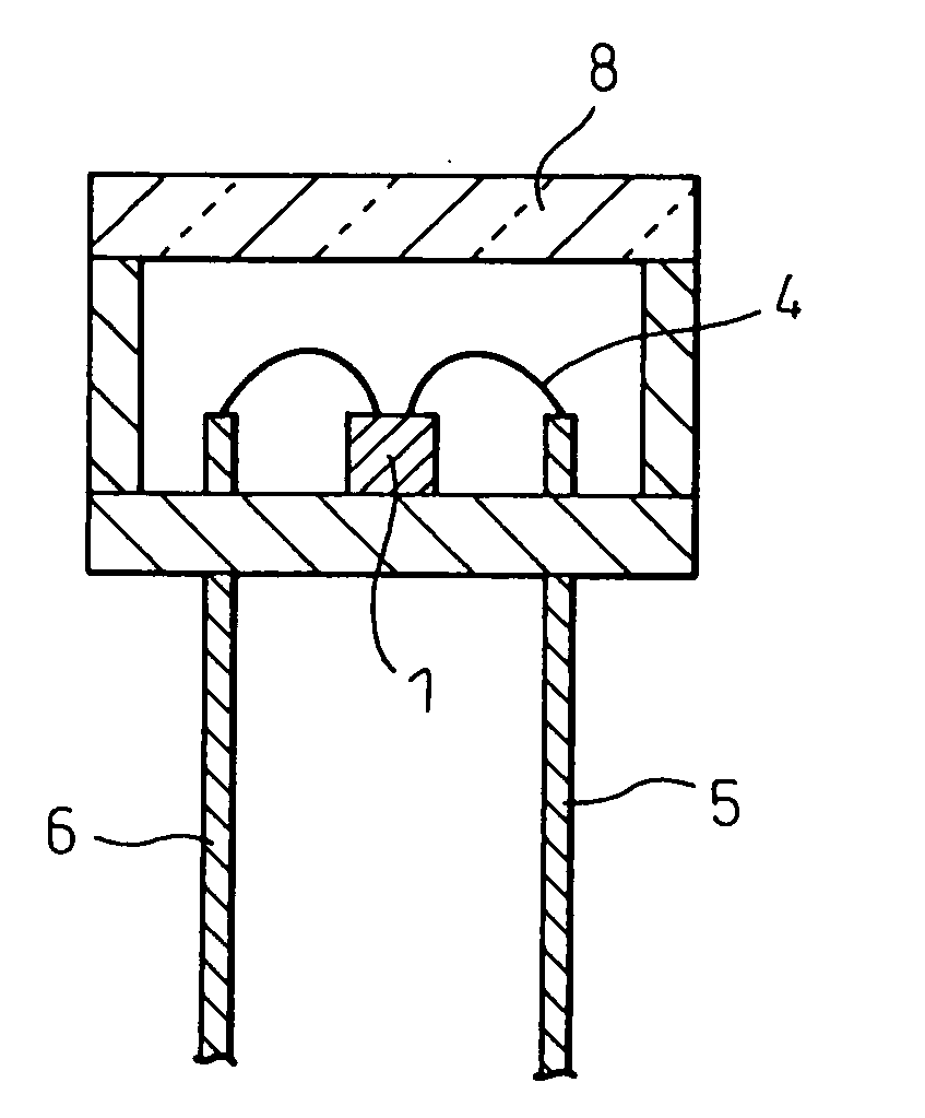
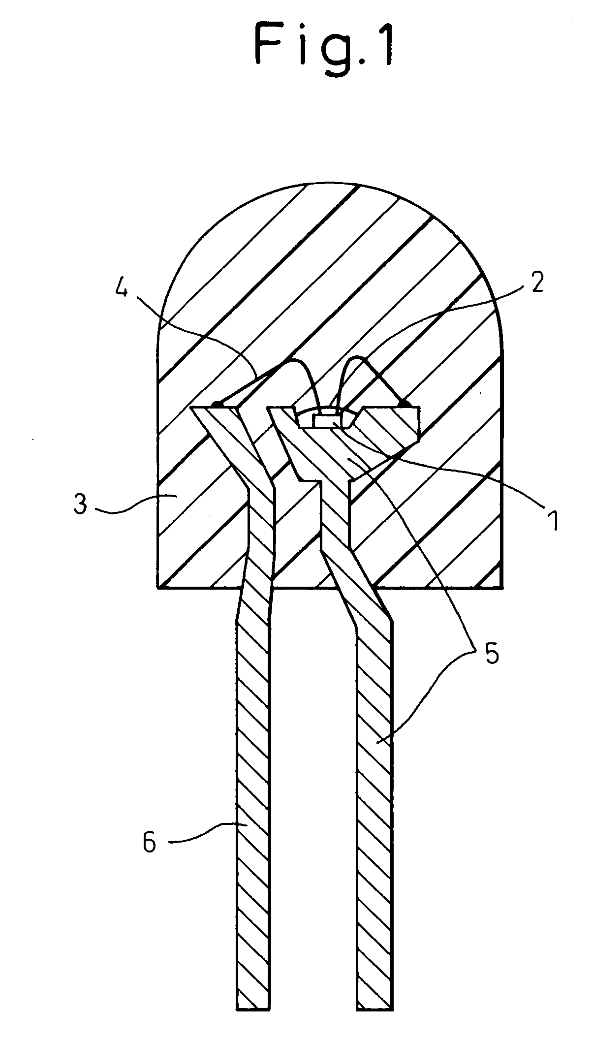
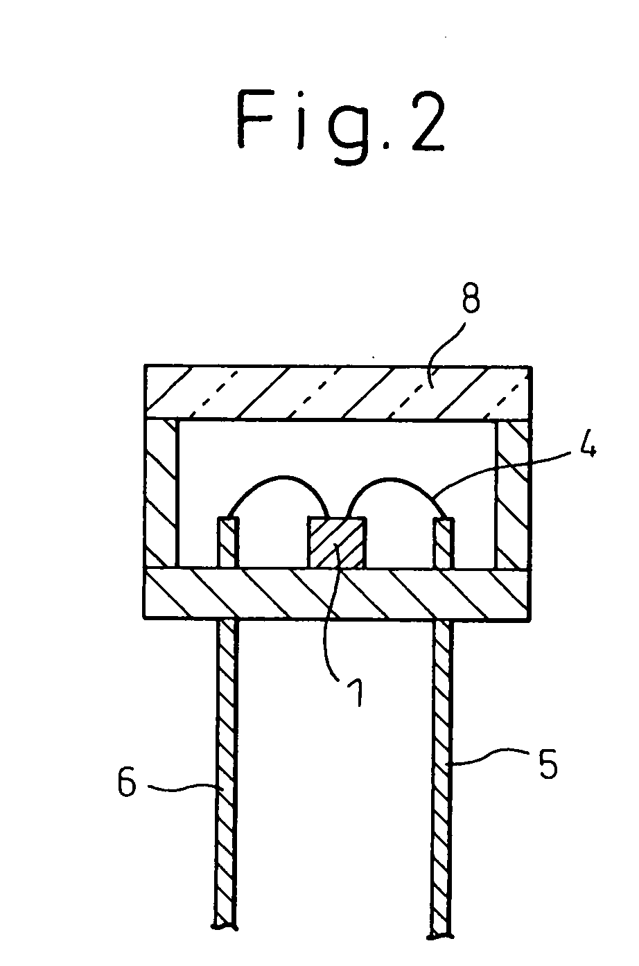
[0069] From the ceramic composite material for light conversion produced in Example 1, a thin plate was cut out by a diamond cutter. This thin plate was processed to produce a disc-like specimen mountable on a light-emitting diode shown in FIG. 2, and a light-emitting diode was fabricated. The wavelength of the blue light-emitting diode chip used was 470 nm. FIG. 10 shows a light emission spectrum of the thus-obtained white light-emitting diode. Blue light at about 470 nm and light at 530 nm emitted from the ceramic composite material for light conversion were observed.

[0070] Furthermore, the color was measured by placing this light-emitting diode in an integrating sphere. As a result, the color of emitted light had CIE chromaticity coordinates of x=0.27 and y=0.34 and was verified to be a white color.


PUM

PropertyMeasurementUnit
Coloraaaaaaaaaa
Wavelengthaaaaaaaaaa
Fluorescenceaaaaaaaaaa

Abstract

A ceramic composite material for light conversion, which is a solidified body comprising two or more matrix phases with respective components being two or more oxides selected from the group consisting of metal oxides and complex oxides each produced from two or more metal oxides, wherein at least one of the matrix phases is a phosphor phase containing an activated oxide. The solidified body is preferably obtained by the unidirectional solidification method. The ceramic composite material for light conversion is excellent in brightness, light-mixing property, heat resistance and ultraviolet light resistance.

Description

TECHNICAL FIELD [0001] The present invention relates to a ceramic composite material, for light conversion, having a function of converting some irradiated light into light at a wavelength different from the irradiated light and at the same time, mixing the converted light with the unconverted irradiated light to cause conversion into light having a color tone different from the irradiated light, and also relates to the use thereof. BACKGROUND ART [0002] With a recent practical implementation of a blue light-emitting diode, studies are being aggressively made to develop a white light source by utilizing this diode as the light emission source. White light is in very large demand as a light source for illumination and, in addition, is greatly advantageous in that a light-emitting diode has a low power consumption and ensures a long life, compared with existing white light sources. [0003] According to this method, the blue light emitted from the blue light-emitting diode is converted ...

Claims


Application Information

Patent Timeline
IPC IPC(8): H01L33/00C04B35/117C04B35/44C04B35/653C09K11/08H01L33/50
CPCC04B35/117C04B35/44H01L2224/8592C04B35/62665C04B35/652C04B35/653C04B2235/3215C04B2235/3217C04B2235/3222C04B2235/3225C04B2235/3229C04B2235/445C04B2235/6581C04B2235/80C09K11/0805H01L33/502H01L2224/48091H01L2224/48247H01L2924/00014H01L2924/181H01L2224/48257H01L2924/00012C04B35/107C09K11/08C04B35/01
Inventor SAKATA, SHIN-ICHIWAKU, YOSHIHARU
Owner UBE IND LTD
Why Eureka
Try Eureka