Horizontal mill

A grinding and drum grinding technology, applied to horizontal grinding. It can solve the problems that the cylinder is prone to radial runout or vibration, affects the normal operation of the support system, and local components are damaged, and achieves the effects of high reliability, reduced noise and damage, and extended service life

Inactive Publication Date: 2006-06-14
郝志刚
View PDF0 Cites 0 Cited by
  • Summary
  • Abstract
  • Description
  • Claims
  • Application Information

AI Technical Summary

Problems solved by technology

However, because it only has one grinding roller, the production efficiency is low; when it is desired to use a high number of revolutions to improve production efficiency, because the support system it sets is only supported on the outer wall of the lower part of the grinding cylinder, the support system only supports the grinding cylinder. The vertical downward direction acts as a constraint, while the other directions along the circumference, especially the upward direction, are in an unlimited free state. Therefore, during the operation, when the medium or high speed operation is used, the cylinder is prone to damage. Radial runout or vibration, resulting in poor stability and high noise during operation; in addition, when the pressure mechanism drives the grinding roller to press the material for grinding, the force generated by the pressure and acting on the grinding cylinder is completely In the downward direction, the force on each part of the equipment is uneven, and the force during pressurization is transmitted through the grinding cylinder and completely acts on the support system, which will affect the normal operation of the support system. Excessive pressurization force will increase the size of the components. Wear and tear, and even cause local components to be damaged

Method used


Image

  • Horizontal mill
  • Horizontal mill
  • Horizontal mill

Examples


Embodiment Construction

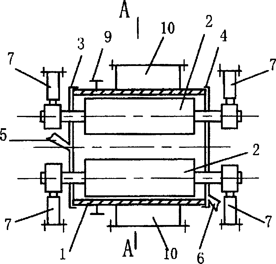
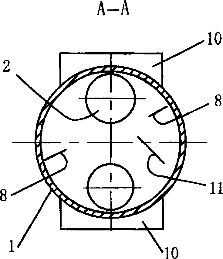
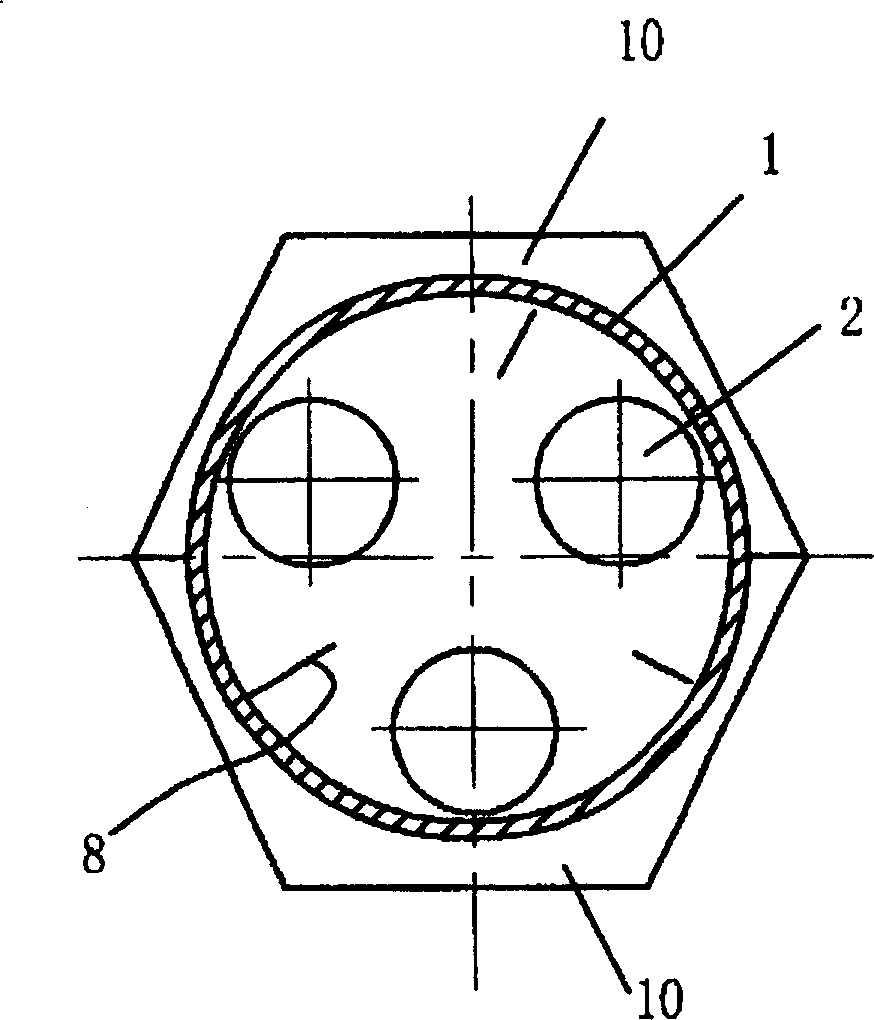
[0017] figure 1 and figure 2 An embodiment of the invention is shown. It includes a grinding cylinder 1 and a grinding roller 2. There are two grinding rollers 2, which are located in the grinding cylinder and arranged symmetrically up and down. The two ends of the grinding cylinder are respectively provided with end covers 3 and 4, and the end cover 3 is provided with a feeding device. 5. There is a discharge port 6 on the end cover 4. The roller surface of each grinding roller and the wall surface corresponding to the inner cavity of the grinding cylinder constitute the material grinding surface, and the shaft sections at both ends of each grinding roller extend out of the end covers at both ends of the grinding cylinder. , the shaft sections protruding from the end covers at both ends are respectively provided with a pressurizing mechanism 7 for adjusting the material roller grinding pressure and adjusting the gap between the grinding roller surface and the inner wall sur...


PUM


Abstract

Horizontal grinding, with a grinding cylinder (1) and a grinding roller (2), the two ends of the grinding cylinder are respectively equipped with end covers (3), (4), and the end cover (3) has a feeding device (5), and the end cover (4) There is a discharge port (6), and the outer wall of the grinding cylinder is provided with a transmission member (9) that drives the grinding cylinder to rotate. The grinding roller is located in the grinding cylinder, and the shaft sections at both ends of the grinding roller protrude The end caps at both ends of the barrel, the two extended shaft sections are provided with a pressure mechanism (7) that can adjust the material roller grinding pressure and the gap between the roller surface and the inner wall of the grinding barrel (7). There are at least two scrapers for the grinding roller (2), which are distributed or evenly distributed along the circumferential direction of the inner chamber of the grinding cylinder. A support system (10) constraining the circumferential direction of the grinding drum.

Description

technical field [0001] The invention belongs to material grinding equipment, in particular to horizontal grinding. Background technique [0002] The "972477373" patent announced on August 25, 1999 discloses a "drum roller mill". The tube roller mill has a grinding cylinder, a support system supported on the outer wall of the lower part of the grinding cylinder, and a grinding roller. The end cover at one end of the grinding cylinder is provided with a feeding device, and the discharge cover (end cover) at the other end of the grinding cylinder ) has a discharge port, the grinding roller is located in the grinding cylinder, the roller surface of the grinding roller and the lower part of the inner cavity of the cylinder form a material grinding surface, and the shaft sections at both ends of the grinding roller protrude from the end of the grinding cylinder respectively. The end cover and the discharge cover are respectively provided with (oil cylinder) pressurizing mechanism...

Claims


Application Information

Patent Timeline
Patent Type & Authority Patents(China)
IPC IPC(8): B02C15/16B02C4/00B02C15/00B02C15/06
CPCB02C15/003B02C15/004B02C15/06B02C15/16
Inventor 郝志刚
Owner 郝志刚
Why Eureka
Try Eureka