
Separated axial flow pump

An axial-flow pump and separate technology, which is applied in the field of medical pumps, can solve the problems of large pre-filling volume, collapse of pump tubes, and poor flexibility, and achieve the requirements of reducing temperature rise, ensuring smoothness, and improving efficiency.

Inactive Publication Date: 2006-06-21
XINHUA HOSPITAL ATTACHED TO SHANGHAI NO 2 MADICALUNIV
View PDF1 Cites 0 Cited by
  • Summary
  • Abstract
  • Description
  • Claims
  • Application Information

AI Technical Summary

Problems solved by technology

However, due to its own following shortcomings, it is not suitable for application in extracorporeal circulation of newborns and young infants: 1. Poor flexibility, it is generally installed on the base, cannot be moved, requires a long pipeline connection, and has a large amount of prefilling
2. The blood is seriously damaged. Due to its extrusion effect, it not only damages the formed components of the blood to a certain extent, but also causes the extruded pipe wall to produce detached debris, which is brought into the human body through the blood flow. Form embolus, affect perfusion effect
3. There is a certain risk, because it is a closed type pump, once the blood flow is blocked, it will generate high pressure behind the pump, causing the pump tube to collapse, and when the blood supply in front of the pump is insufficient, it will also A large amount of gas is pumped into the body with serious consequences
However, most of the existing blood pumps and their motors are integrated or directly connected with flexible shafts, which not only brings a lot of inconvenience to their one-time use, but also greatly increases the cost of their one-time use.

Method used


Image

  • Separated axial flow pump
  • Separated axial flow pump
  • Separated axial flow pump

Examples


Embodiment Construction

[0035] Now, a detachable axial flow pump of the present invention will be further described in detail in conjunction with specific embodiments.

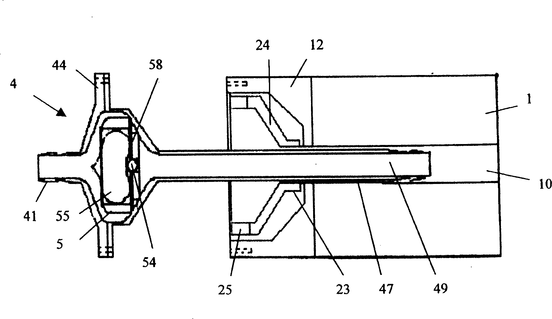
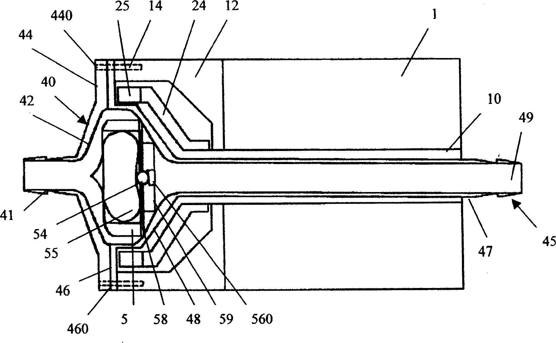
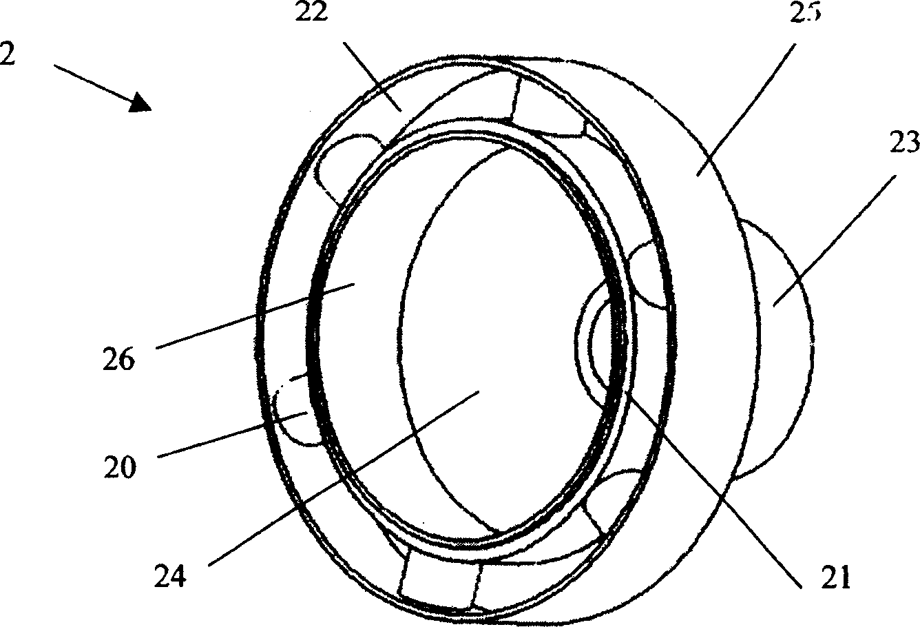
[0036] refer to figure 1 and figure 2 , the detachable axial flow pump of the present invention includes a driving device (not fully shown and labeled) and a pump body 4, and the pump body 4 is provided with an inlet port (not labeled), an outlet port (not labeled), an inner magnet 5 and an impeller 55 . The inlet end, the outlet end of the pump body 4 and the impeller 55 are on the same central axis, and the pump body 4 is detachably installed axially on the central axis of the driving device; the impeller 55 is fixedly arranged in the inner magnet 5, and the driving device A transmission device (not labeled) is provided inside, which includes the outer magnet 2 that can be magnetically coupled with the inner magnet 5 to drive the impeller 55 to rotate.

[0037] Wherein, the pump body 4 includes a first vertebral body 45 , a secon...


PUM


Abstract

The present invention relates to a detachable axial flow pump suitable for use in extracorporeal circulation in infant surgery, which includes a driving device and a pump body, the pump body is provided with an inlet end, an outlet end, an inner magnet and an impeller; the inlet of the pump body If the pump end, the outlet end and the impeller are on the same central axis, the pump body can be detachably installed axially on the central axis of the drive device; the impeller is fixed in the inner magnet, and a transmission device is installed in the drive device, which includes The inner magnet is magnetically coupled to drive the outer magnet of the impeller to rotate. The invention adopts a detachable structure, so that the pump body can meet the requirements of one-time use, and the motor can be used repeatedly, thereby reducing the cost of clinical use.

Description

technical field [0001] The invention relates to a medical pump, especially a detachable axial-flow pump suitable for use in extracorporeal circulation in infant surgery. Background technique [0002] With the continuous improvement of surgical techniques and the in-depth development of various researches, the concept that congenital heart disease should be treated as soon as possible to prevent various secondary lesions has gradually formed. The age of patients undergoing surgery continues to decline, and more and more patients are being operated on in infancy or even in the neonatal period. This also puts forward higher requirements for cardiopulmonary bypass technology, requiring more advanced equipment that is more suitable for infant bypass. [0003] General cardiopulmonary bypass equipment is mainly medical pumps and oxygenators. Cardiopulmonary bypass for young infants requires the equipment used to have the following characteristics: 1. Low precharge. The amount of ...

Claims


Application Information

Patent Timeline
Patent Type & Authority Patents(China)
IPC IPC(8): F04D13/02A61M1/10
Inventor 丁文祥俞晓青王伟
Owner XINHUA HOSPITAL ATTACHED TO SHANGHAI NO 2 MADICALUNIV
Learn More