

Method for recognizing and correcting errors
An error identification and error technology, applied in the direction of error prevention, transmission system, electrical components, etc., can solve the problem of inability to distinguish error types, etc., and achieve the effect of reliable error elimination
- Summary
- Abstract
- Description
- Claims
- Application Information
AI Technical Summary
Problems solved by technology
Method used
Image

Examples
Embodiment 1
[0023] In operating point 1 and zone 1 of the diagnostic characteristic curve family, existing errors can be correctly identified. In operating point 2 and area 2 of the diagnostic characteristic map, the existing error cannot be recognized.
[0024] Under this condition, an error is identified at the operating point BP1 and a compensation measure is initiated. For this knock recognition embodiment, for example, the error of the knock sensor is recognized, and the ignition angle is adjusted not according to the output signal of the sensor, but according to a predeterminable compensation value. After the error recognition, the operating point changes. This error cannot be recognized in operating point 2. However, because the error recognition is realized in the area B1, the error elimination is cut off. Thus, the error remains recognized and the compensation measures keep working. If the error disappears in the process of continuing the operation, the error elimination cannot be real...
Embodiment 2
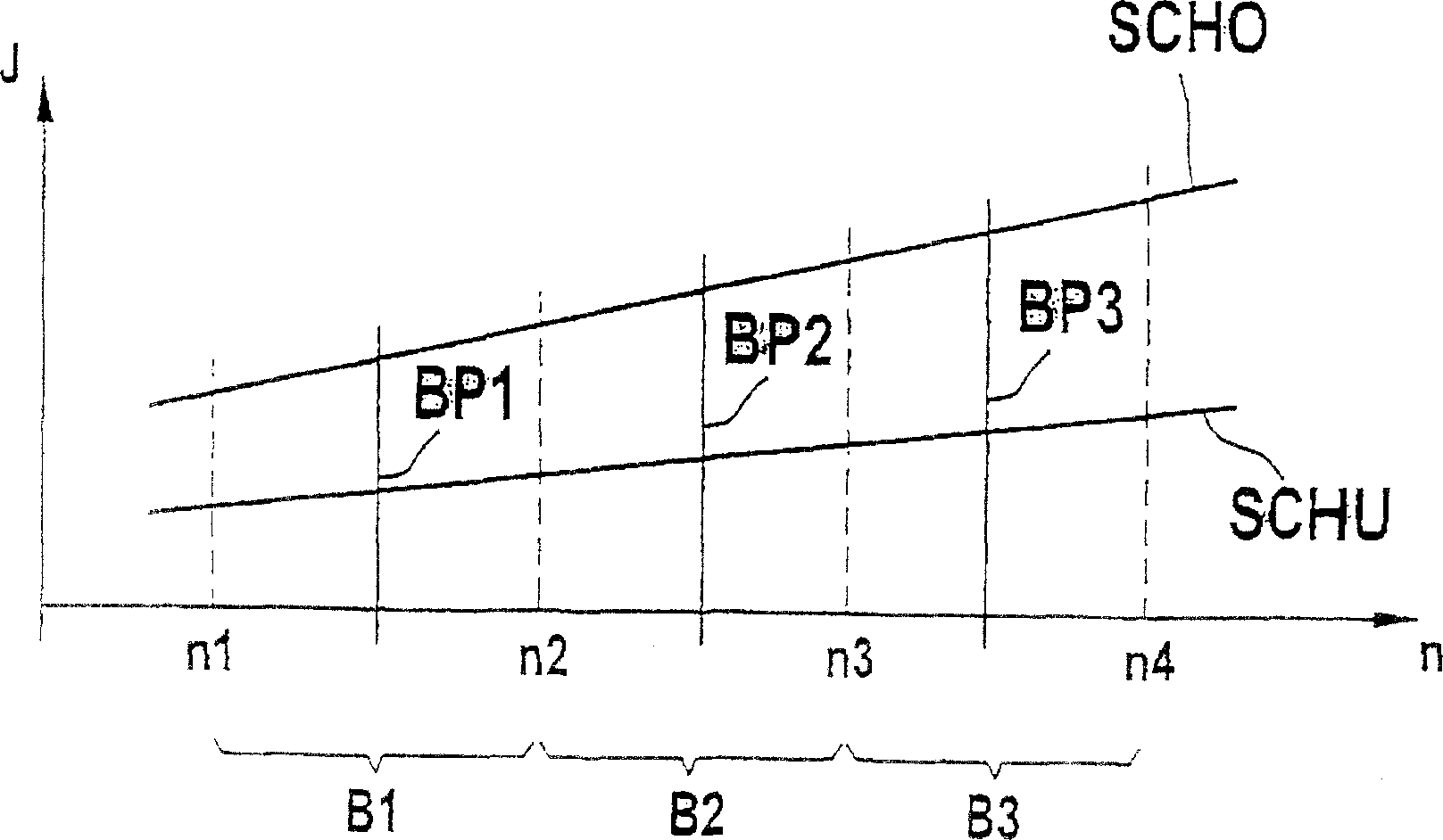
[0026] In the operating point BP1 and the operating point BP3, that is, in the areas B1 and B3 of the diagnostic characteristic curve family, an existing error can be correctly identified. However, the existing error cannot be recognized in the operating point BP2 and the area B2 of the diagnostic characteristic curve family.
[0027] In this case, the error is identified at the operating point BP1 and a compensation measure is initiated. Then switch to working point BP2. According to the example given, the error cannot be recognized there. In this way, the error elimination is cut off because the error recognition is realized in the area B1. Thus, as long as it is in the operating point BP2, the error remains recognized and the compensation measures remain active. This error can be recognized when switching to the working point BP3 next. Because the error has been identified in the area B1 and the compensation measures have been initiated, you only need to pay attention at this t...
Embodiment 3
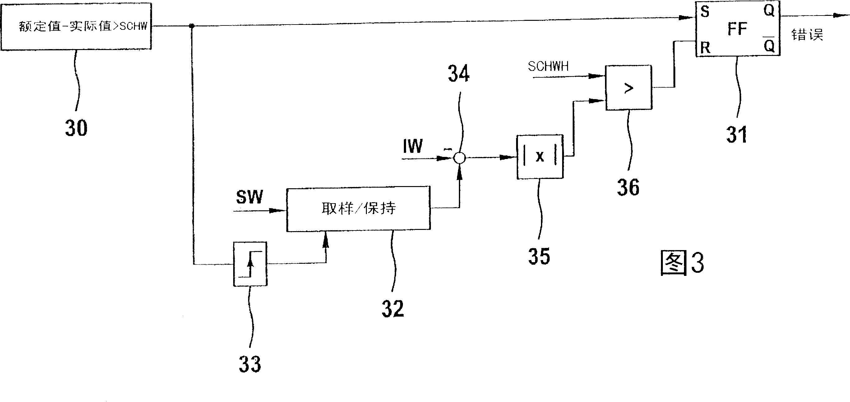
[0030] In Embodiment 3, it is explained in detail that the error type is considered when the error is eliminated. In Embodiment 3, the premise is that the monitored signal is located between the two thresholds SCHO and SCHU. If the signal is higher than the upper threshold, it is recognized as an error with an error type of MAX error. If it is lower than the lower threshold, it is recognized as an error whose error type is MIN error. In the operating point BP1, that is to say in the area B1, not only the MIN error but also the MAX error can be recognized. In contrast, only MIN errors can be identified in the operating point BP2.
[0031] In the operating point BP1, the signal is below the lower threshold, an error of the MIN error type is recognized and a compensation measure is initiated. Then switch to working point BP2. Here, it is also recognized as an error of the MIN error type. In this way, the error remains recognized and the compensation measures keep working. In the next...
PUM
 Abstract
Description
Claims
Application Information