Anti-counterfeiting fingerprint identification device and fingerprint identification method

A fingerprint recognition and fingerprint collector technology, applied in character and pattern recognition, user identity/authority verification, instruments, etc., can solve the problems of large size, cannot exclude false fingerprint reading, and high production cost

Active Publication Date: 2011-04-06
熵基科技(广东)有限公司
View PDF4 Cites 49 Cited by
  • Summary
  • Abstract
  • Description
  • Claims
  • Application Information

AI Technical Summary

Problems solved by technology

However, the existing fingerprint identification technology and products still have the following disadvantages that do not meet the needs: the fingerprint identification device can be compared successfully by using the plastic imprint copy of the identifiable finger, so the reading of

Method used


Image

  • Anti-counterfeiting fingerprint identification device and fingerprint identification method
  • Anti-counterfeiting fingerprint identification device and fingerprint identification method
  • Anti-counterfeiting fingerprint identification device and fingerprint identification method

Examples


specific Embodiment approach 1

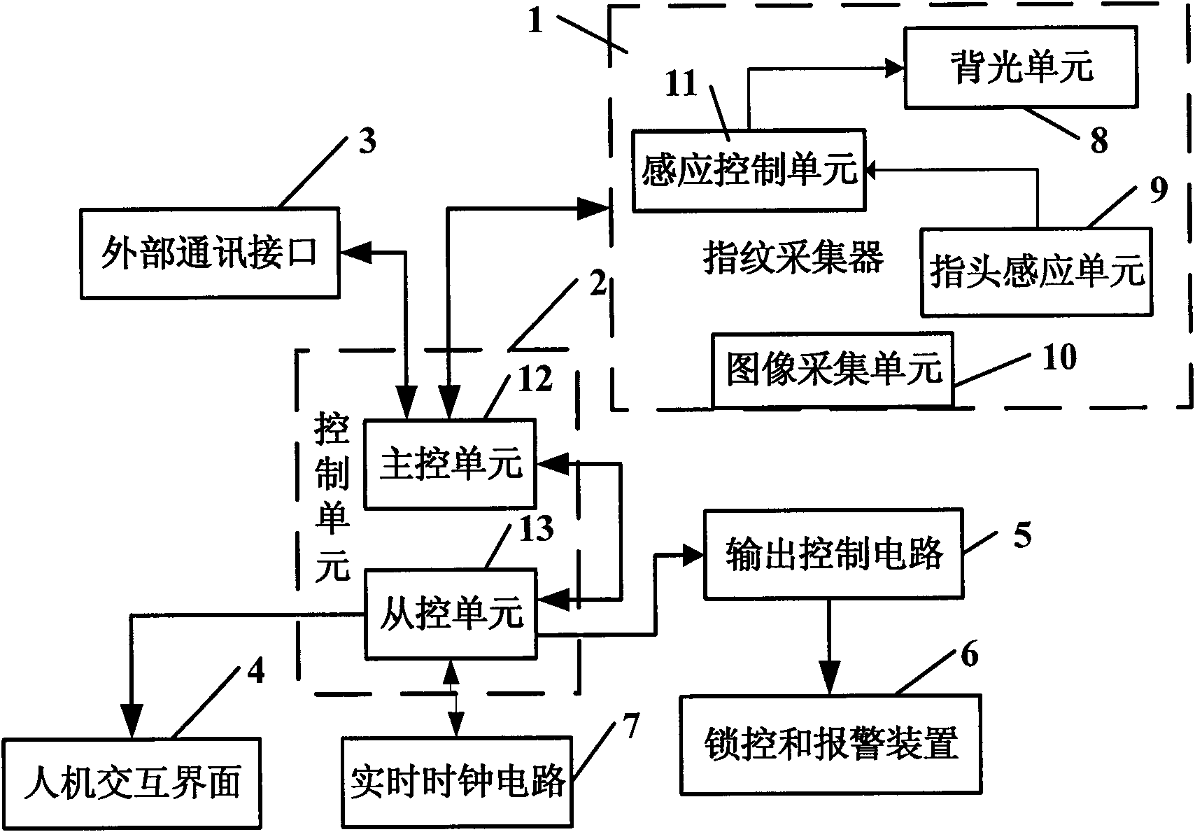
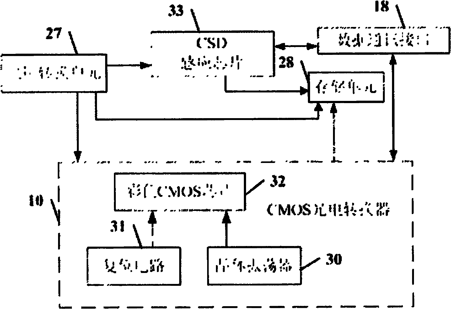
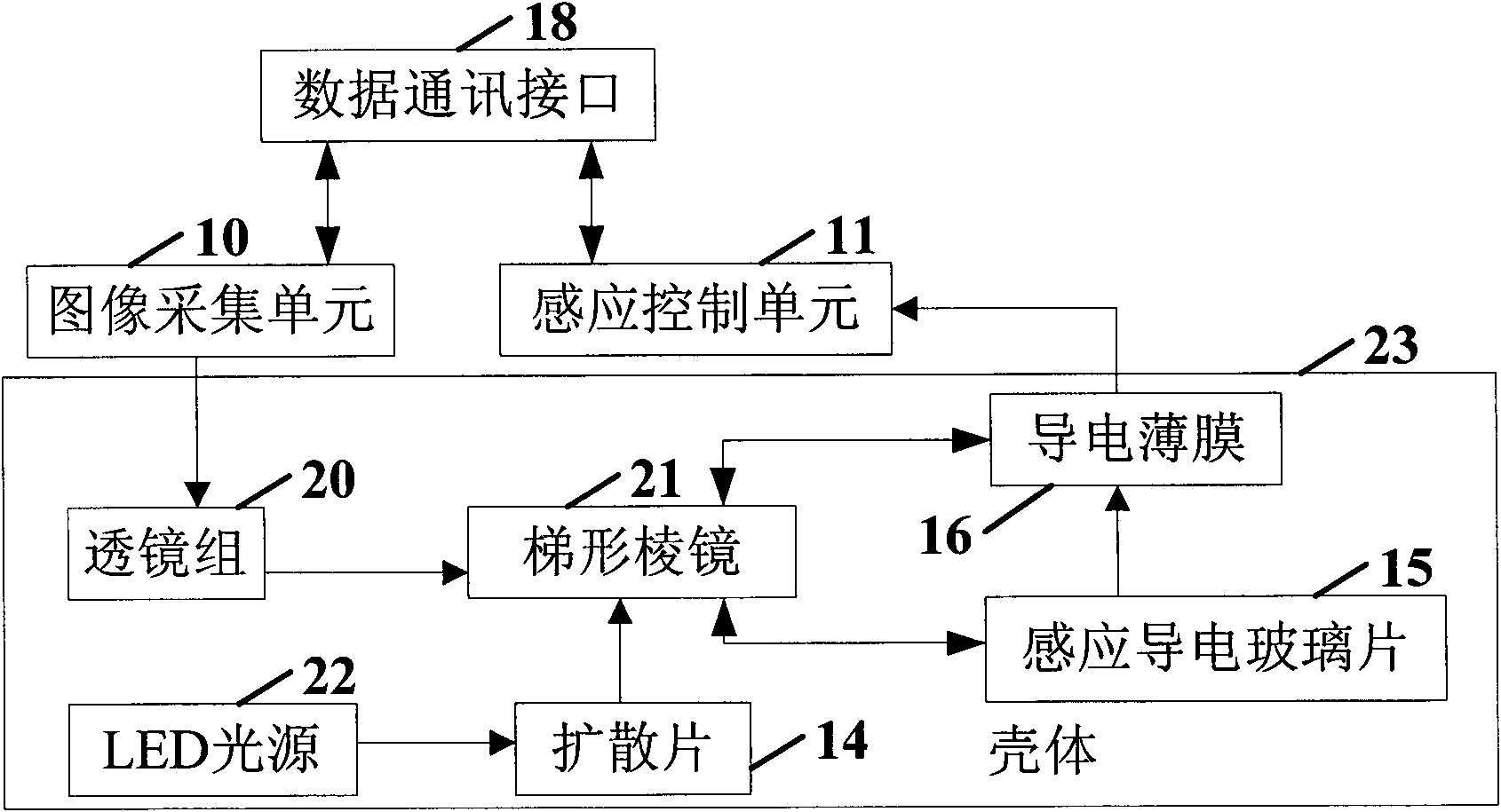
[0071] An anti-counterfeit fingerprint identification device as shown in 1 to 9 as shown in the figure, comprising a fingerprint collector body, the fingerprint collector body includes a housing 23, an image acquisition unit 10, a finger sensing unit 9, a sensing control unit 11, and a backlight unit 8, and a data communication interface 18. The finger sensing unit 9 includes a regular cuboid conductive film 16 and a sensing conductive glass sheet 15, the conductive film 16 is connected to the sensing control unit 11, the sensing conductive glass sheet 15 is connected to the trapezoidal prism 21, and UV glue is used to connect the sensing conductive glass sheet 15 to the trapezoidal prism. The image acquisition surface of the prism 21 is attached, and the transparent electrode conductive layer of the induction conductive glass sheet 15 is connected with one end of the long side of the conductive film 16 to form a touch sensing capacitance C sensor .

[0072] The backlight uni...

specific Embodiment approach 2

[0115] Another anti-counterfeiting fingerprint identification device has basically the same composition as the first embodiment, the difference is that the finger sensing unit 9 does not include a sensing conductive glass sheet 15 . One side of the conductive film 16 is attached to the upper side of the upper side of the trapezoidal prism 21 coated with a black paint layer for light-shielding by indium plating technology, and forms a touch sensing capacitance C with the trapezoidal prism 21 sensor . The induction efficiency can be improved and the manufacturing cost can be saved by not using the induction conductive glass sheet.

[0116] The anti-counterfeit fingerprint identification method of the second embodiment is the same as that of the first embodiment.


PUM


Abstract

The invention discloses an anti-counterfeiting fingerprint identification device and an anti-counterfeiting fingerprint identification method. The device is provided with a sense control unit which comprises a CapSenseSigma-Delta (CSD) chip, wherein the CSD sense chip is connected with a conductive film. Fingerprints of living organisms are judged by recording an increment in the CSD sense chip and summating numeric codes converted by a modulator. The fingerprint identification method comprises the following steps in turn: 1) initializing; 2) circuit self-checking; 3) performing a corresponding program according to information input by a user; 4) judging whether to communicate; 5) acquiring image data; and 6) comparing registered users. The device of the invention has low cost, can outputa signal by touching lightly, does not need to adopt any distortion correction optical element, and can reduce manufacturing cost and realize miniaturization; the linear distortion relationship obtained by comparing an acquired fingerprint image with an actual fingerprint image can be corrected by software; and therefore, the device has the advantages of high quality of acquired optical imaging image, high fingerprint identification reliability, low error identification rate, good effect on anti-counterfeiting fingerprints, simple structure and low power consumption.

Description

technical field [0001] The invention relates to a device or method for fingerprint identification using an electronic circuit, in particular to an anti-counterfeiting fingerprint identification device and a fingerprint identification method thereof. Background technique [0002] Among the existing identification technologies based on physiological characteristics, fingerprint identification technology is currently the most mature one. However, the existing fingerprint identification technology and products still have the following disadvantages that do not meet the needs: the fingerprint identification device can be compared successfully by using the plastic imprint copy of the identifiable finger, so the reading of false fingerprints cannot be ruled out, and the fingerprint The structure of the collector is relatively complex, the volume is large, and the production cost is high. In addition, the fingerprint image distortion and correction process are not perfect, resulting...

Claims


Application Information

Patent Timeline
IPC IPC(8): G06K9/00
CPCH04L9/32
Inventor 车全宏仲崇亮林晓清
Owner 熵基科技(广东)有限公司
Why Eureka
Try Eureka