
Motor rotor

A technology of electric motors and synchronous motors, which is applied to electric components, synchronous motors with stationary armatures and rotating magnets, electrical components, etc., can solve problems such as noise, rotor vibration, and large torque changes, and achieve increased magnetic flux and improved Changes in torque and the effect of improving magnet torque

Inactive Publication Date: 2006-07-26
YAMAHA MOTOR CO LTD
View PDF0 Cites 2 Cited by
  • Summary
  • Abstract
  • Description
  • Claims
  • Application Information

AI Technical Summary

Problems solved by technology

[0007] However, since the induced voltage waveform of the winding on the stator facing the magnet in the surface magnet type contains a large number of harmonics, the torque variation (torque ripple) of the motor becomes large, which causes rotor vibration and vibration-induced noise

Method used


Image

  • Motor rotor
  • Motor rotor
  • Motor rotor

Examples


Embodiment Construction

[0034] Embodiments of the present invention will now be described in detail with reference to the accompanying drawings.

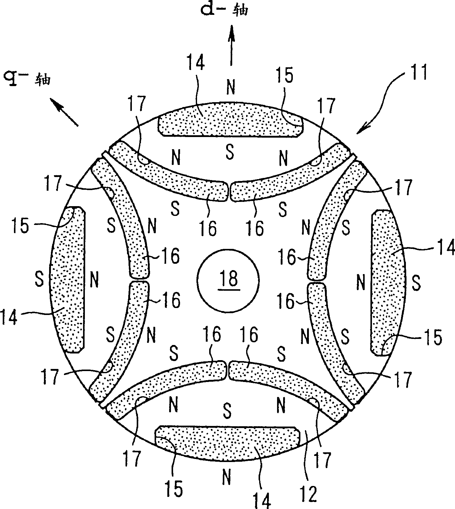
[0035] The structure of a first embodiment of the motor rotor of the present invention will be described below with reference to FIG. 1. FIG.

[0036] The rotor of the first embodiment is used in a permanent magnet type synchronous motor, and adopts a matching relationship with a known stator (not shown) of a permanent magnet type synchronous motor.

[0037] As shown in FIG. 1, the rotor 11 comprises a ferromagnetic core 12, which is a laminated steel plate block 13, made, for example, of silicon steel plates of a certain thickness. A certain number of permanent magnets 14 (for example, four pieces) are installed on the outer surface of the core 12 at certain intervals along the circumferential direction.

[0038] More specifically, four notches 15 are circumferentially provided on the outer surface of the core 12, and the permanent magnets 14 are firmly ...


PUM


Abstract

To provide a rotor for a motor capable of effecting improved torque variation due to improvement in the induced voltage waveform and of effecting improved magnet torque in a permanent magnet type synchronous motor utilizing reluctance torque. A rotor 11 comprises of a core 12 made of a ferromagnetic material, a given member of permanent magnets 14 are mounted in the outer surface of the core 12 circumferentially at equal intervals, and arrangement of the permanent magnets 14 is such that polarities N, S of the permanent magnets on the sides facing a stator are disposed alternately. Also, in the core 12 between the center axis of the core and the permanent magnets 14 are embedded arc-shaped permanent magnets 16 corresponding to the permanent magnets 14, respectively, and arrangement of the permanent magnets 16 is the same as that of the corresponding permanent magnets 14.

Description

technical field [0001] The present invention relates to motor rotors such as permanent magnet type synchronous motors (PM motors) used on electric car bodies. Background technique [0002] Heretofore, there has been known a permanent magnet type synchronous motor system in which the rotor has magnetic protrusions to effectively utilize the reluctance torque, which is classified into a buried magnet type and a surface magnet type according to the structure of the rotor. [0003] The embedded magnet type has a structure in which permanent magnets are embedded in the rotor, and constitutes a permanent magnet type synchronous motor utilizing reluctance torque. [0004] On the other hand, in the structure of the surface magnet type, as an example, the rotor 1 is arranged as shown in FIG. 10 . The rotor 1 includes a core 2 made of ferromagnetic material. Permanent magnets 3 are stuck on the outer surface of the core 2 at certain intervals, and protrusions 4 are arranged between t...

Claims


Application Information

Patent Timeline
Patent Type & Authority Patents(China)
IPC IPC(8): H02K1/27H02K1/22H02K21/22
CPCH02K1/274H02K1/276H02K1/278H02K1/246
Inventor 内藤真也日野阳至
Owner YAMAHA MOTOR CO LTD
Learn More