Supercharge Your Innovation With Domain-Expert AI Agents!

Pulse width modulation method for permanent magnet brushless DC motor

A permanent magnet brushless DC, pulse width modulation technology, applied in the direction of excitation or armature current control, can solve the problem of aggravating the electromagnetic torque ripple of the motor, reduce the electromagnetic torque ripple problem, eliminate the freewheeling current, The effect of increasing the stability

Inactive Publication Date: 2006-08-09
ZHEJIANG UNIV
View PDF0 Cites 0 Cited by
  • Summary
  • Abstract
  • Description
  • Claims
  • Application Information

AI Technical Summary

Problems solved by technology

[0002] The existing PWM (Pulse Width Modulation) modulation technology for permanent magnet brushless DC motor (stator winding star connection), when the motor is driven by a three-phase half-bridge inverter and works in 120-degree conduction mode, it will During the non-commutation period, make the terminal voltage of the non-conductive phase higher than the DC bus voltage or lower than zero voltage, which will cause the non-conductive phase to generate freewheeling current and aggravate the electromagnetic torque ripple of the motor

Method used


Image

  • Pulse width modulation method for permanent magnet brushless DC motor
  • Pulse width modulation method for permanent magnet brushless DC motor
  • Pulse width modulation method for permanent magnet brushless DC motor

Examples


Embodiment Construction

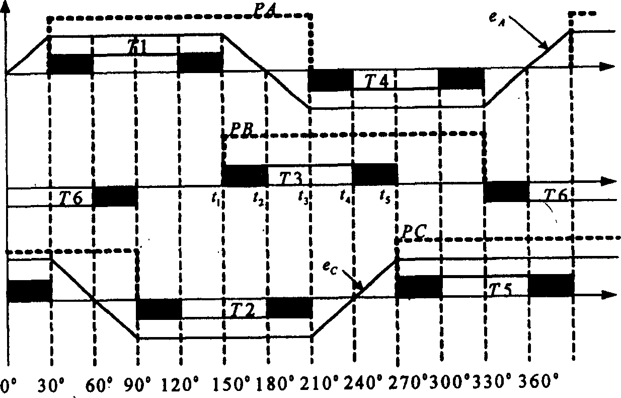
[0011] figure 1 It is a schematic diagram of the PWM_ON_PWM modulation method proposed by the present invention. The shaded part is the area for PWM modulation. In the figure, T1~T6 respectively represent the trigger pulse waveforms of the corresponding switch tubes; the thick dotted lines PA, PB and PC respectively represent the position signals output by the Hall rotor position sensor of the brushless DC motor; e A 、e C Indicate the back electromotive force waveforms on phases A and C respectively; for each switching tube trigger pulse, the modulation area is the first 30° electrical angle of the trigger pulse width and the last 30° electrical angle of the trigger pulse width, and the middle of the trigger pulse width The electrical angle of 60° is not modulated and keeps constant flow. Take the T3 tube as an example to illustrate the implementation method, and the trigger pulse implementation principle of other switching tubes is the same.

[0012] On the rising edge of...


PUM


Abstract

This invention discloses a pulse width modulation method used in permanent magnetic brush-less DC motor, which is put forward against the shortage of the current PWM method. The PWM-ON-PWM method is suitable for the pulse width modulation when a brush-less DC motor works at 120deg. electric angle, each switch tube is in 120deg. trigger pulse width, the front 30deg. interval modulates the pulse width, the mid 60deg. interval keeps constant conduction and the rear 30deg. interval modulates the pulse width, which can eliminate the continuous current on non-conductive phase in the period of non-phase switch to increase the smooth operation of the motor.

Description

technical field [0001] The invention relates to a pulse width modulation method applied to a permanent magnet brushless direct current motor. Background technique [0002] The existing PWM (Pulse Width Modulation) modulation technology for permanent magnet brushless DC motor (stator winding star connection), when the motor is driven by a three-phase half-bridge inverter and works in 120-degree conduction mode, it will During the non-commutation period, the terminal voltage of the non-conducting phase is higher than the DC bus voltage or lower than zero voltage, which will cause the non-conducting phase to generate freewheeling current and aggravate the electromagnetic torque ripple of the motor. Contents of the invention [0003] The purpose of the present invention is to provide a kind of pulse width modulation method that is applied to the permanent magnet brushless DC motor for the above-mentioned existing deficiencies in the PWM modulation method, i.e. PWM_ON_PWM (puls...

Claims


Application Information

Patent Timeline
Patent Type & Authority Patents(China)
IPC IPC(8): H02P7/29
Inventor 张仲超韦鲲
Owner ZHEJIANG UNIV
Features
  • R&D
  • Intellectual Property
  • Life Sciences
  • Materials
  • Tech Scout
  • Unparalleled Data Quality
  • Higher Quality Content
  • 60% Fewer Hallucinations
Learn More