
Thread wiring terminal

A terminal and screw thread technology, which is applied in the field of screw terminals, can solve problems such as unbalanced terminals and achieve the effect of improving balance

Inactive Publication Date: 2006-08-23
SCHNEIDER ELECTRIC IND SAS
View PDF1 Cites 0 Cited by
  • Summary
  • Abstract
  • Description
  • Claims
  • Application Information

AI Technical Summary

Problems solved by technology

[0004] However, the U-shape in the pressure device causes an imbalance in the use of the terminal block

Method used


Image

  • Thread wiring terminal
  • Thread wiring terminal
  • Thread wiring terminal

Examples


Embodiment Construction

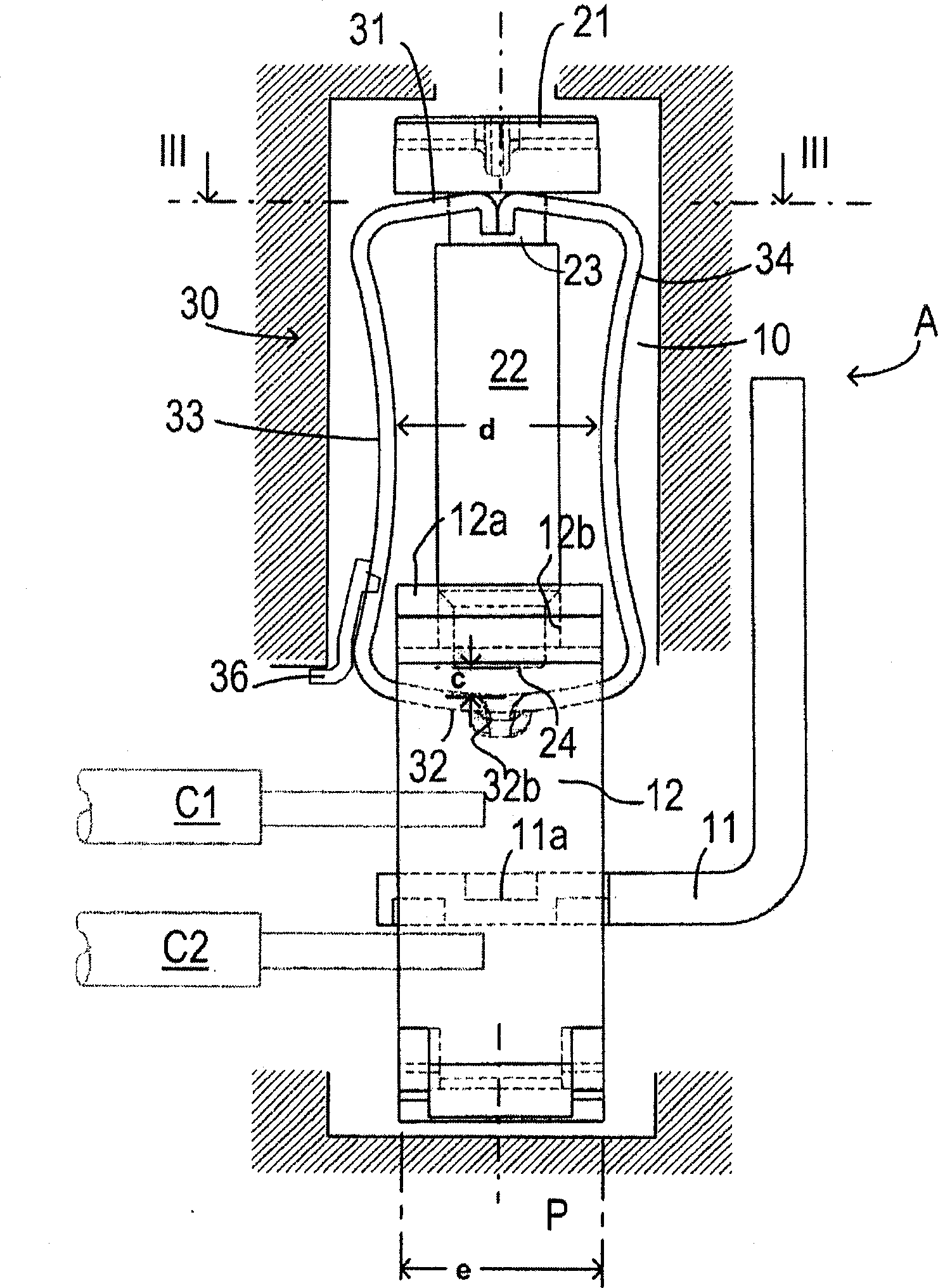
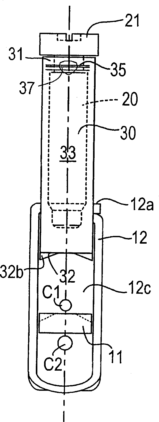
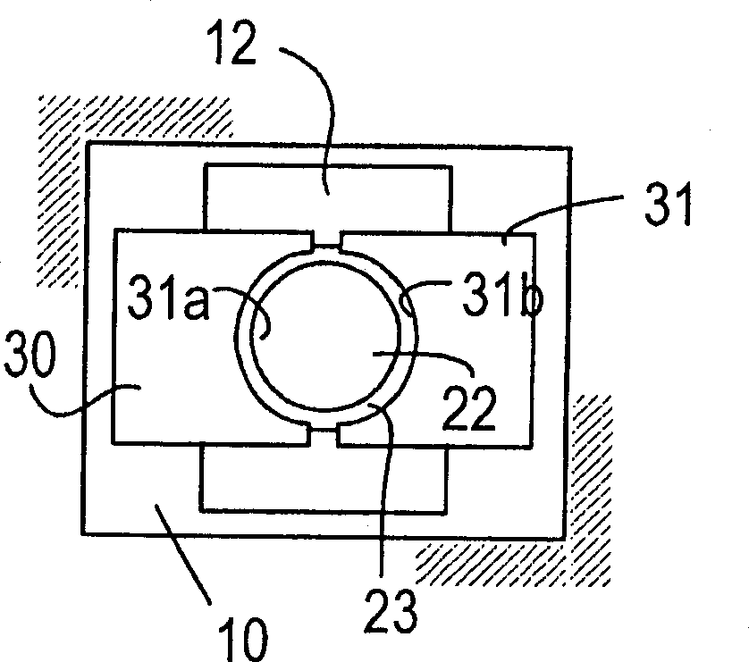
[0014] The screw terminal A shown in the picture is ready to be installed on electrical equipment. figure 1 Only the following elements of the device are shown in the figure: an insulating housing 10 designed for connection terminals, and a fixed connection branch of the rigid conductor device 11, one or several conductors can be screwed on the connection branch and fixed. With this method, figure 1 Shows two conductors c1 and c2 inserted above and below the branch respectively. The housing 10 is located in the electrical equipment, that is, it is designed in a certain part of the equipment housing or fixed to a lug on the equipment housing.

[0015] The terminal A is composed of a common type of connecting frame 12, which is formed by cutting and bending a metal sheet to form a rectangular rigid ring. On the short side 12a, the rigid connecting frame 12 has a tapping hole 12b, and the connection of the conductor device 11 is crossed into the rectangular elongated hole 12c of th...


PUM


Abstract

Screw terminal connected to a conductor device mounted on a piece of electrical equipment to connect at least one conductor, composed of a connection cage and a screw, the cage and / or the screw being movable inside the terminal housing. A pressure device (30) composed of a head plate (31) and a pressure plate (32) connected to each other by two elastic symmetrical wings (33, 34) designed to store torque energy, the head plate being convex in shape and attached by the screw neck. The pressure plate can be applied against a conductor or against the conductor device on the equipment, and the elastic wings are concave in shape, with a concavity that is reduced as the pressure on the screw is increased.

Description

Technical field [0001] The invention relates to a threaded terminal connected to a conductor device of an electrical equipment, for connecting at least one electrical conductor to the device. technical background [0002] In particular, it relates to a threaded terminal, which includes a connection frame provided with a tapping hole, a screw with a threaded head and a rod screwed into the tapping hole, and an elastic pressure device for acting on an electric conductor. The connecting frame and / or screw can move in the housing of the electrical equipment, and the pressure device includes a top plate and a pressure plate connected by elastic wings that store torque energy. The top plate bears the pressure from the screw head, and the pressure plate acts on the conductor or The conductor element of the device. [0003] The document DE U 1935560 describes this type of terminal block. A U-shaped stirrup pressure device, including a high wing and a low wing conn...

Claims


Application Information

Patent Timeline
Patent Type & Authority Patents(China)
IPC IPC(8): H01R4/36H01R4/38H01R4/48
CPCY10T403/7041H01R4/489H01R4/363
Inventor 乔斯·加西亚瑟奇·帕吉赫维·格里洛特丹尼斯·巴塞农维尔
Owner SCHNEIDER ELECTRIC IND SAS
Learn More