Paper separation friction pad

A friction pad and paper technology, applied in the field of friction pads, can solve the problems of high operating power and high cost

Inactive Publication Date: 2006-10-04
LEXMARK INT INC
View PDF0 Cites 0 Cited by
  • Summary
  • Abstract
  • Description
  • Claims
  • Application Information

AI Technical Summary

Problems solved by technology

However, as mentioned earlier, a center-driven system requires a higher cost for it...

Method used


Image

  • Paper separation friction pad
  • Paper separation friction pad
  • Paper separation friction pad

Examples


Embodiment Construction

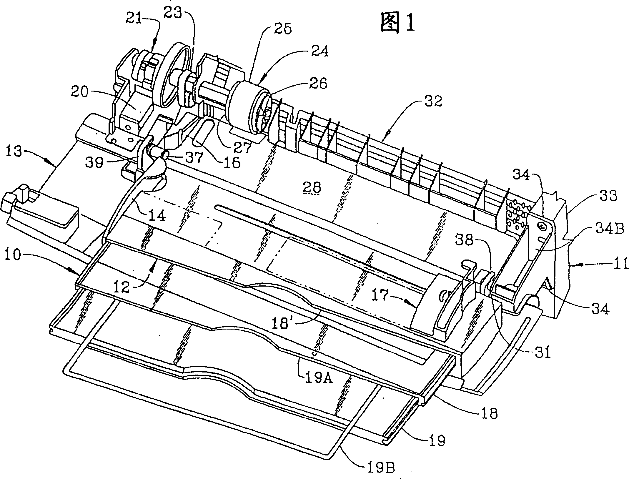
[0031] Referring to the Figures and in particular to Figure 1, there is shown a paper feeding device 10 of a printer 11. Paper feeder 10 includes a tray assembly 12 mounted on a swingably mounted door 13 of printer 11 .

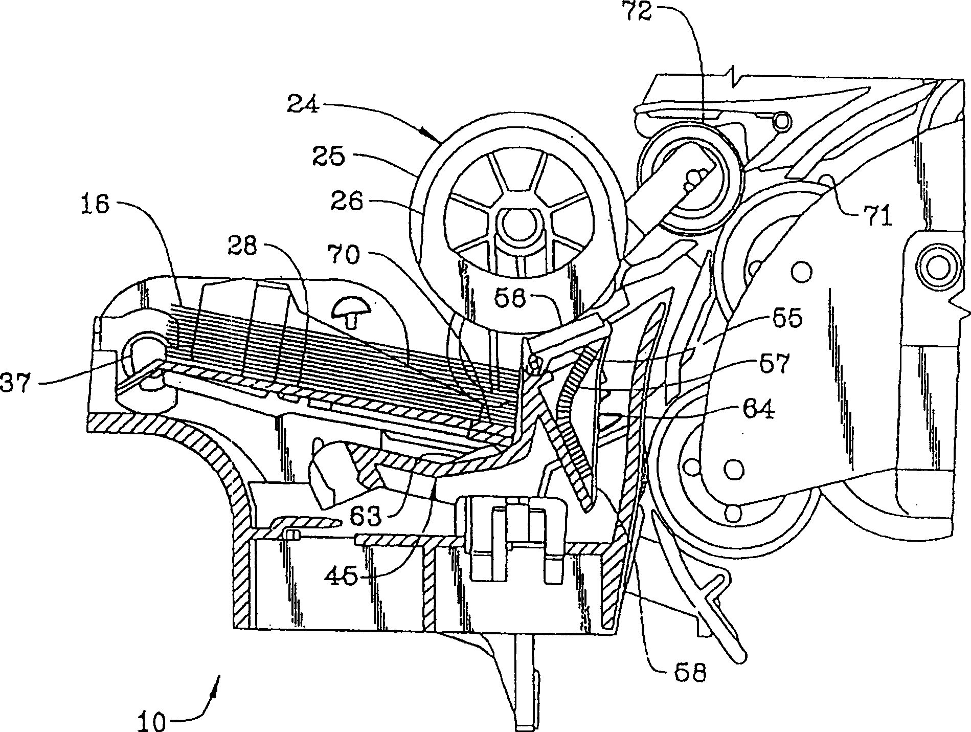
[0032] Tray assembly 12 has datum edge 14 and 15, and each media (16) is as paper (see image 3 )'s left edge rests on it as it advances. When sheets or stacks are placed in the tray assembly 12 (see Fig. 1), - a movable paper guide 17 (see Fig. 1) engages the right edge of each sheet 16 (see image 3 ). Thus, the paper feeder 10 employs an edge alignment system to align a stack of paper 16 (see image 3 ) into the printer (see Figure 1).

[0033] The tray assembly 12 includes a first slider 18 slidable in an opening 18 ′ and a second slider 19 slidable in an opening 19A in the first slider 18 . A wire 19B is fixed on the second slider 19 to pull it out from the first slider 18 until the stopper (not shown) in the second slider 19 and the stopper on the ...


PUM


Abstract

A sheet feeding apparatus having an edge aligned system always maintains a nip between an intermittently driven pick roll and a friction or separator pad. When a top sheet of a stack is being advanced by the pick roll, a first spring exerts a first force on the friction or separator pad to enable advancement and separation of the top sheet. When the pick roll is stopped, a second spring exerts a second forces substantially smaller than the first force on the friction or separator pad but sufficient to maintain the nip between the pick roll and the friction or separator pad to retard any underlying sheet.

Description

technical field [0001] The present invention relates to a paper feeding device in which more than the top sheet of media is prevented from being fed from a stack of paper so that only one sheet is fed to a processing station; more particularly, to a friction pad which Used to exert different forces on the pick-up rollers of the paper feed device depending on where the paper has been fed along its feed path. Background technique [0002] Friction-separation pick-up mechanisms are commonly used in printers and copiers, for example, to feed a sheet onto feed rollers that forward the sheet to the processing station of the printer or copier. A typical friction-separation pick-up mechanism includes a spring-loaded lifter, a high-friction pick-up roller, and a spring-loaded separation pad. [0003] The separation pad is formed of a material that has a coefficient of friction with the paper that is greater than the coefficient of friction between adjacent papers but less than that ...

Claims


Application Information

Patent Timeline
IPC IPC(8): B65H3/52B41L21/02B41J13/00G03G15/00
CPCB65H3/5223B65H2515/34B65H2220/11B65H2220/04
Inventor 丹尼尔·P·卡希尔爱德华·A·拉什斯科特·S·威廉斯
Owner LEXMARK INT INC
Why Eureka
Try Eureka