Feeding mechanism and spinning device

A technology of feeding mechanism and raw material box, applied in the field of spinning processing, can solve the problem of labor and other problems, and achieve the effect of reducing manual participation and avoiding excessive fatigue.

Active Publication Date: 2021-03-26
HUBEI UNIV OF TECH
View PDF17 Cites 2 Cited by
  • Summary
  • Abstract
  • Description
  • Claims
  • Application Information

AI Technical Summary

Problems solved by technology

[0004] In view of this, it is necessary to provide a feeding mechanism and a spinning device to solve the technical problem of laborious loading and unloading of spinning machines in the prior art

Method used


Image

  • Feeding mechanism and spinning device
  • Feeding mechanism and spinning device
  • Feeding mechanism and spinning device

Examples


Embodiment Construction

[0037] Preferred embodiments of the present invention are specifically described below in conjunction with the accompanying drawings, wherein the accompanying drawings constitute a part of the application and are used together with the embodiments of the present invention to explain the principle of the present invention, and are not intended to limit the scope of the present invention.

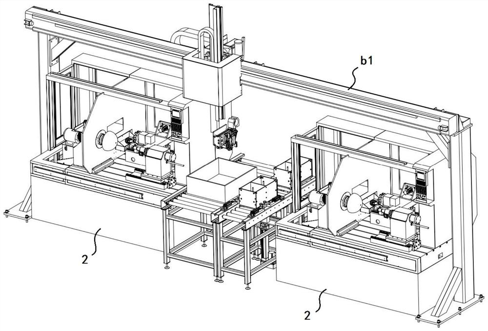
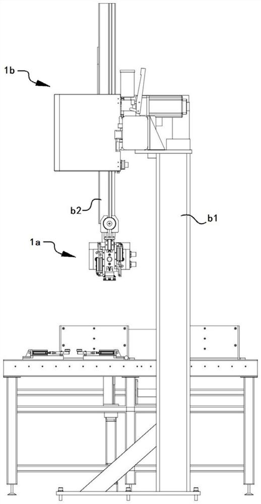
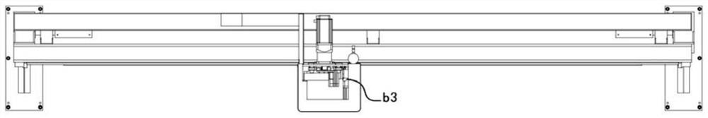
[0038] The invention provides a spinning device, such as Figures 1 to 19 As shown, it includes a feeding mechanism 1 and two spinning machines 2. The feeding mechanism 1 includes a clamping assembly 1a, a moving assembly 1b and a raw material conveying assembly 1c. The clamping assembly 1a includes a connecting seat a1, a suction cup a2, and a clamping piece a3 , the first rotating part a4, the first driving part a5 and the second driving part a6, the output end of the first rotating part a4 is connected to the connecting seat a1 for driving the connecting seat a1 to rotate, the suction cup p...


PUM


Abstract

The invention discloses a feeding mechanism comprising a clamping assembly and a moving assembly, the clamping assembly comprises a connecting base, a first rotating piece, a suction cup piece, a clamping piece, a first driving piece and a second driving piece, the output end of the first rotating piece is connected to the connecting base and used for driving the connecting base to rotate, and thesuction cup piece and the clamping piece are both rotationally connected to the connecting base. The rotating axes of the suction cup piece and the clamping piece are parallel to each other and perpendicular to the rotating axis of the output end of the first rotating piece, the suction cup piece is used for sucking materials, the clamping piece is used for clamping the materials, the first driving piece and the second driving piece are both fixed to the connecting base, and the output ends of the first driving piece and the second driving piece are connected to the suction cup piece and theclamping piece respectively. The moving assembly comprises a support and a first lifting piece, the fixed end of the first lifting piece is connected to the support and can move relative to the support, and the output end of the first lifting piece is connected to the fixed end of the first rotating piece. Manual participation in feeding and discharging of a spinning machine can be reduced.

Description

technical field [0001] The invention relates to the technical field of spinning processing, in particular to a feeding mechanism and a spinning device. Background technique [0002] When the spinning machine is forming metal parts such as metal cups and lampshades, it first sucks and fixes the metal sheet on one side, and then pushes the metal sheet to fit the mold corresponding to the shape of the lamp cup to form the metal lamp cup . [0003] At present, when the spinning machine is used for processing, the loading and unloading of the spinning machine is done manually. When loading and unloading, the manual has been repeating the mechanized action, which is laborious after a long time. Contents of the invention [0004] In view of this, it is necessary to provide a feeding mechanism and a spinning device to solve the technical problem of laborious loading and unloading of spinning machines in the prior art. [0005] In order to achieve the above technical purpose, the...

Claims


Application Information

Patent Timeline
Patent Type & Authority Applications(China)
IPC IPC(8): B21D43/02B21D43/18B21D45/02B21D22/14
CPCB21D43/027B21D43/18B21D45/02B21D22/14Y02P70/62
Inventor 夏军勇刘科进钟飞严国平周宏娣李博
Owner HUBEI UNIV OF TECH
Why Eureka
Try Eureka