Composite type card connector

一种连接器、卡插入的技术,应用在连接、混合阅读器、连接装置的零部件等方向,能够解决安装高度变大、碰伤卡、插拔耐久性减少等问题

Inactive Publication Date: 2006-11-29
YAMAICHI ELECTRONICS
View PDF1 Cites 0 Cited by
  • Summary
  • Abstract
  • Description
  • Claims
  • Application Information

AI Technical Summary

Problems solved by technology

However, in the technique of the above-mentioned publication, in order to allow two different types of cards to be inserted and used in the same multi-connector for cards, it is necessary to perform detailed processing on the cards.
[0005] In addition, it can also be seen that since the overall length, width, and thickness of the card are different in size and size, when setting the contacts suitable for the card, the displacement of the contacts is large when inserting a large card, and when plugging and unplugging In the case of a large card, the card will be damaged by these contacts, and the contact part of the contact will be greatly cut off, which will cause the decrease in plug-in durability. Moreover, in order to prevent the bending of the contact, it is necessary The actual installation height will be increased due to the back groove provided at the front end, etc.

Method used


Image

  • Composite type card connector
  • Composite type card connector
  • Composite type card connector

Examples


Embodiment 1

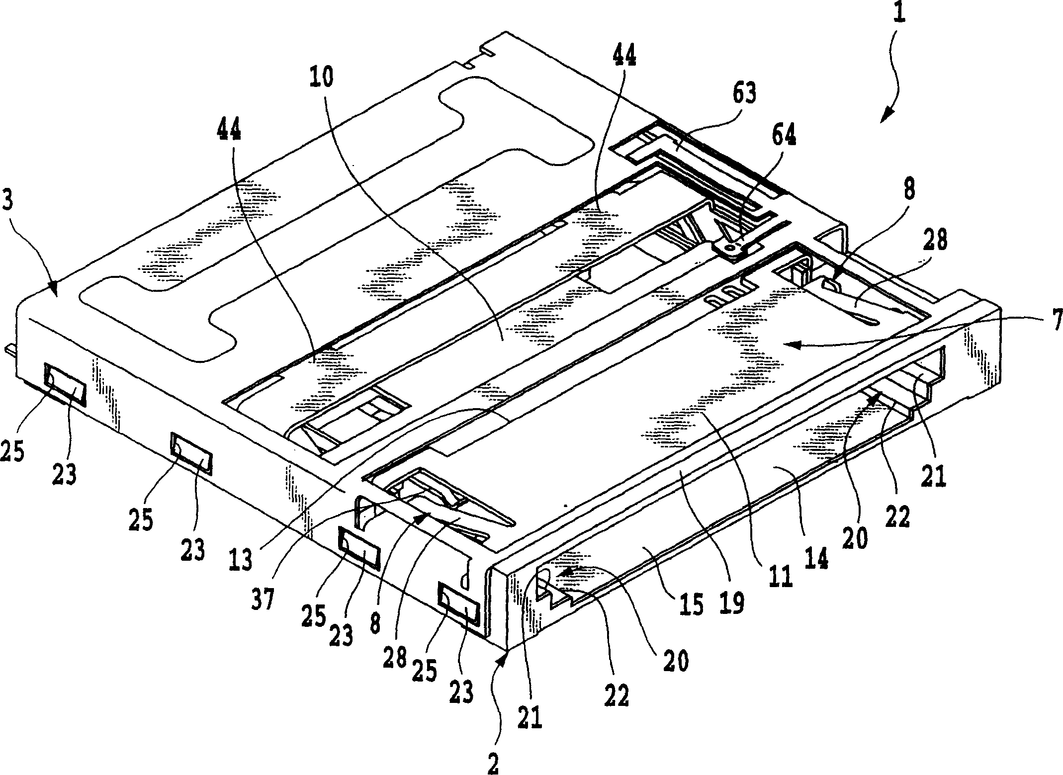
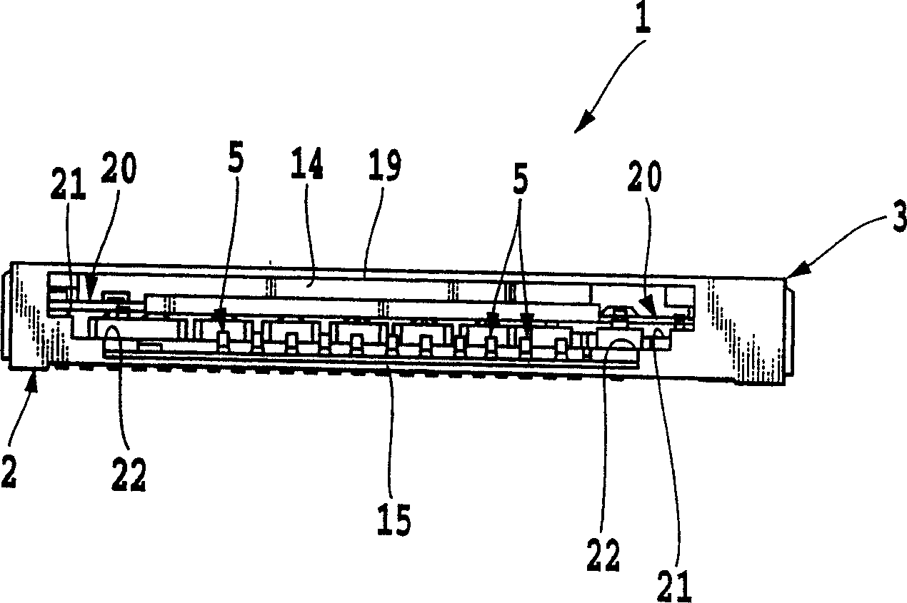
[0085] Figure 1 to Figure 10 is a diagram showing Example 1 of the composite card connector of the present invention, figure 1It is a perspective view of the whole composite connector for cards of the present invention viewed from the side of the card insertion port, figure 2 is its top view, image 3 It is an end view seen from the card slot side, Figure 4 yes and right figure 1 The composite connector for a card of the present invention is represented by removing the cover member and figure 1 The same stereogram, Figure 5 is to indicate Figure 4 The perspective view of the enlarged part of the locking mechanism part of the composite card connector of the present invention, Image 6 is to remove Figure 4 The top view of the cover member of the composite card connector of the present invention, Figure 7 is its side view, Figure 8 It is a bottom view seen from the lower side, Figure 9 is to remove the cover Figure 4 The perspective view of the composite car...

Embodiment 2

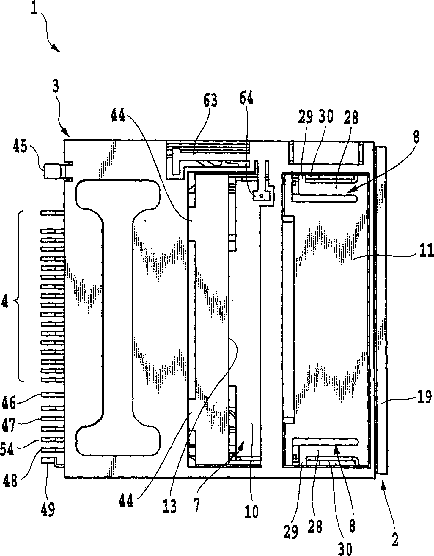
[0142] Figure 41 to Figure 54 is a diagram showing the second embodiment of the card composite connector of the present invention, Figure 41 It is a perspective view of the whole composite connector for cards according to the second embodiment of the present invention as seen from the side of the card insertion port, Figure 42 is true Figure 41 A perspective view of the card composite connector with the cover part removed, Figure 43 is true Figure 41 A perspective view of the card composite connector with further removal of the cover member and the movable plate and the operation plate, Figure 44 is from with Figure 43 The same perspective view viewed from the opposite side, Figure 45 is true Figure 41 The end view of the card composite connector according to the second embodiment of the present invention is shown from the side of the card insertion port when the cover member, the movable plate and the operation plate are removed, and FIG. 46 is a pair of Fig...


PUM


Abstract

A composite type card connector of the present invention includes a connector body, a cover member, first contact members for a small card, second contact members for a large card, and a switching operation mechanism having a movable plate and a operating plate, such that a card-mounting section in the connector body is switched to another one by the switching operation mechanism so that two kinds of cards different in thickness and / or width can be commonly inserted into the same composite type card connector.

Description

technical field [0001] The present invention relates to a composite connector for cards, and relates to electronic devices such as mobile phones, telephones, PDAs (personal digital assistance), game machines, notebook computers, walkmans, televisions, video recorders, digital cameras, etc. or information terminals. A composite card connector for machines, in particular, relates to a composite card connector capable of using two types of cards of different sizes. Background technique [0002] In recent years, in electronic equipment such as mobile phones, telephones, PDAs (personal digital assistance), game machines, notebook computers, Walkmans, televisions, video recorders, digital cameras, and information terminals, what is called a CPU or a computer has been incorporated. The use of IC cards, PC cards, SD cards, SIM cards, etc., of IC chips for memory, IC components, etc., is increasing very rapidly, so that small-scale memory that inserts IC cards, PC cards, SD cards, SI...

Claims


Application Information

Patent Timeline
Patent Type & Authority Patents(China)
IPC IPC(8): H01R27/00H01R13/629G06K17/00G06K7/00G06K13/08H01R13/633
CPCG06K7/0021G06K13/0825G06K13/08G06K13/0806G06K7/0043H01R12/7005H01R27/00G06K13/0887G06K7/0013G06K7/0004
Inventor 佐藤繁高居阳介
Owner YAMAICHI ELECTRONICS
Why Eureka
Try Eureka