Disc recording-playing device

A disc, detection device technology, used in recording information storage, instruments, etc.

Inactive Publication Date: 2006-12-13
SONY CORP
View PDF2 Cites 0 Cited by
  • Summary
  • Abstract
  • Description
  • Claims
  • Application Information

AI Technical Summary

Problems solved by technology

[0003] However, when the disc is in the standby mode, the process of writing information to the disc and reading information from the disc is temporarily interrupted, and the driver circuit of the focusing objective lens is not energized, and the above method of avoiding the contact between the objective lens and the disc cannot be implemented.

Method used


Image

  • Disc recording-playing device
  • Disc recording-playing device
  • Disc recording-playing device

Examples


Embodiment Construction

[0020] A disc recording and reproducing apparatus using an optical disc mounted in a cartridge case (hereinafter referred to as a "disc case") according to a preferred embodiment of the present invention will be described below.

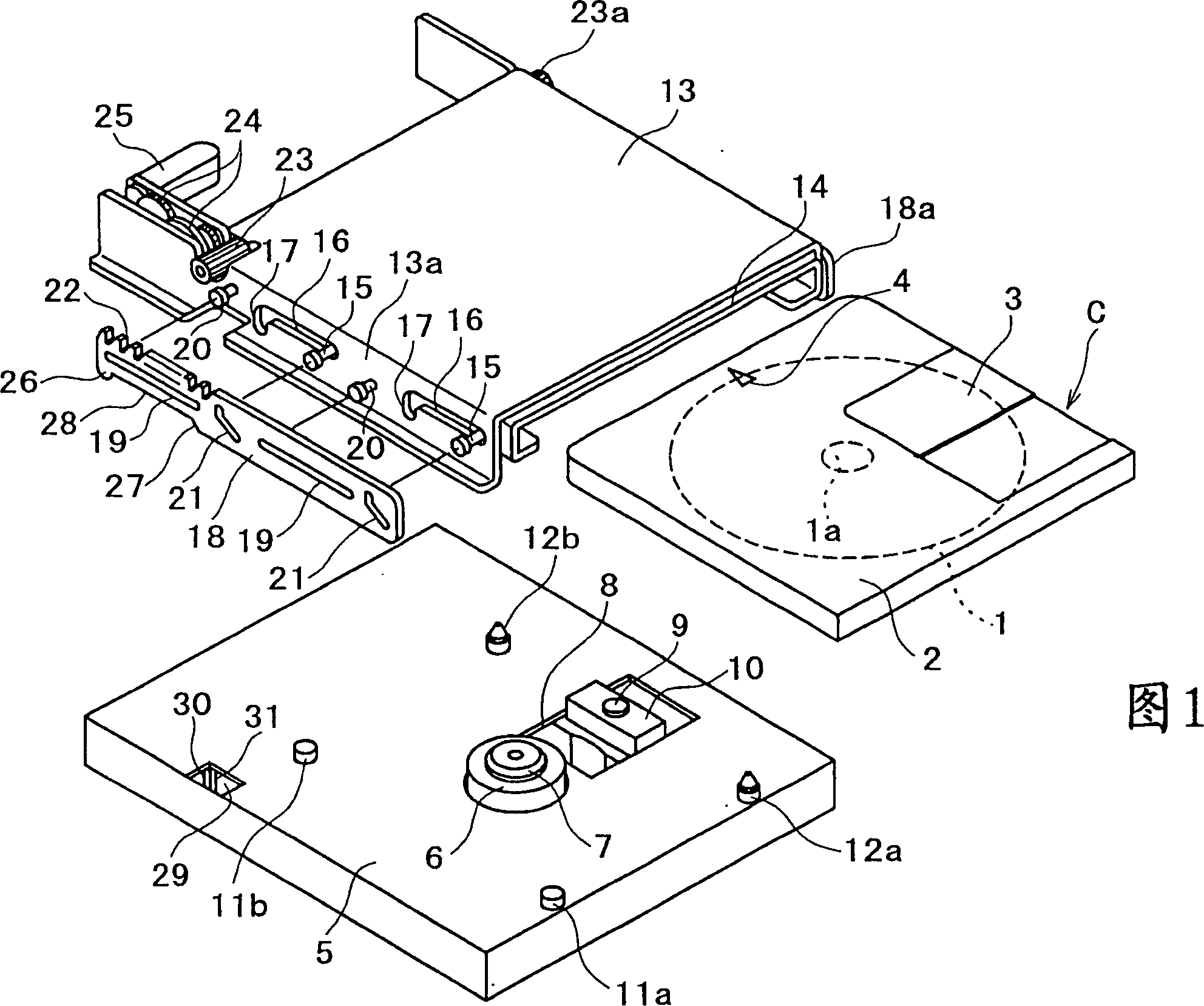
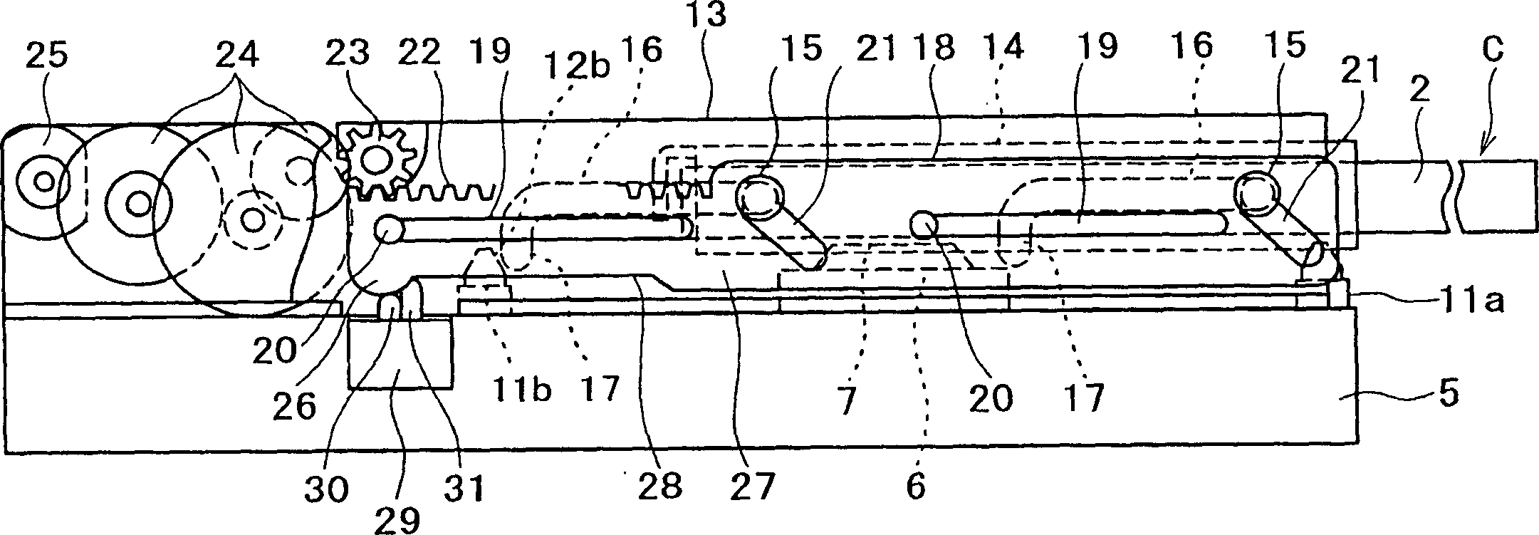
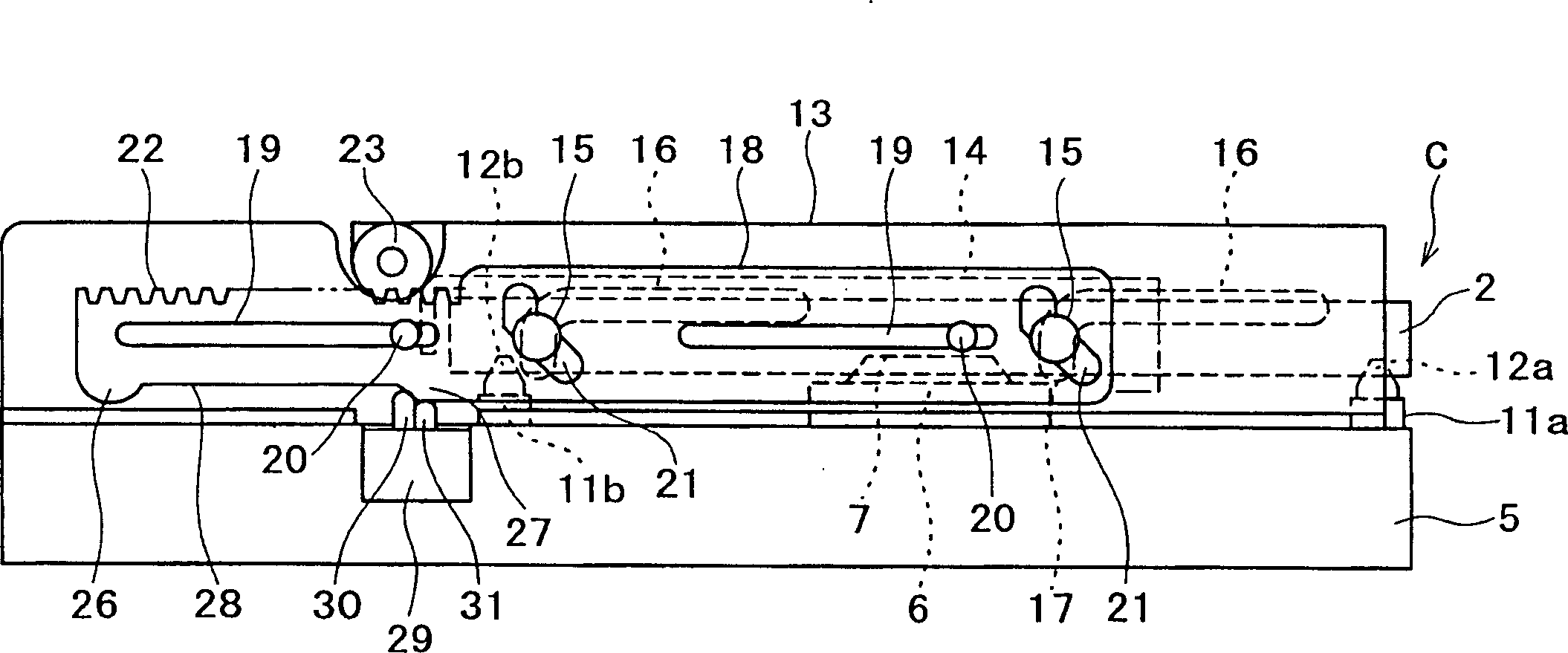
[0021] First, a description will be given of a disc cartridge C used as a recording medium with reference to FIGS. 1 to 4 .

[0022] As shown in FIGS. 1 to 4, a disc case C has an optical disc (hereinafter referred to as a "disc") 1 rotatably mounted in a case 2 comprising an upper case half and a lower case which are integrally connected to each other. half box. On one side of the box case 2, a shutter plate 3 that can be selectively in an open position and a disconnected position is installed. When the shutter plate 3 moves to the open position, the window holes defined in the radial direction of the disc 1 in the upper and lower half boxes are opened, exposing the radial portion of the disc 1 . Then, a magnetic head (not shown) applies a bias vo...


PUM


Abstract

A disk recording and reproducing device keeps a disk in a standby position spaced from the objective lens of an optical pickup to prevent the objective lens from contacting the surface of the disk even when the objective lens is moved within a movable range because the disk recording and reproducing device are subjected to vibrations, shocks, or the like. The disk recording and reproducing device has a slide plate slidable by a drive element through a rack. When the slide plate slides, the disk is pulled in a horizontal direction from a disk ejecting position and thereafter is lowered vertically and positioned in a disk writing/reading position in which information can be written on and read from the disk by an optical pickup. The slide plate has switch triggers, and a switch having contact pins detectable by the switch triggers is mounted on a chassis. While the disk is moving from the disk writing/reading position toward the disk ejecting position, one of the contact pins is operated by the switch trigger of the slide plate, and the disk is held in a disk standby position which is spaced a predetermined distance from the objective lens of the optical pickup.

Description

technical field [0001] The present invention relates to disc recording and playback devices, such as compact discs or the like, and more particularly to a disc recording and playback device that uses The puck is kept in a standby position at a distance from the objective lens of the optical sensor so that the objective lens and the puck are prevented from coming into contact with each other. Background technique [0002] In recent years, the objective lens of an optical sensor tends to have a larger numerical aperture to achieve a higher storage density and a larger storage capacity of an optical disc. Since the focal length of the objective lens is reduced due to the larger numerical aperture of the objective lens, the distance between the objective lens and the disc surface, i.e. the working distance, is reduced. During recording or playback of information from the disc, in some cases the working distance is less than the distance the objective lens can move to control fo...

Claims


Application Information

Patent Timeline
Patent Type & Authority Patents(China)
IPC IPC(8): G11B17/04G11B17/043
CPCG11B17/0434G11B17/04
Inventor 山口正人安藤伸彥
Owner SONY CORP
Why Eureka
Try Eureka