Switch, botton switch and rotation switch

A switch and button technology, which is applied in the direction of electric switches, electrical components, contact engagement, etc., can solve the problems of inability to obtain movement amount, reduce balance contacts, and contact performance degradation, etc., and achieve small size, proper spring function, and high-efficiency configuration Composition, the effect of reducing the number of parts

Inactive Publication Date: 2006-12-13
ORMON CORP
View PDF1 Cites 1 Cited by
  • Summary
  • Abstract
  • Description
  • Claims
  • Application Information

AI Technical Summary

Problems solved by technology

[0012] However, in this SPDT type switch, when only one contact structure of normally closed or normally open is selected, although the other contact structure of the unused side is not used at all, the unused contact is still installed. parts, it forms an uneconomical door switch, which also occupies a relatively high proportion in terms of cost
[0013] For this reason, it is considered to omit the contact parts on the unused side in advance. At this time, the space saved by not using a contact part will be generated in the housing, and the movable contact piece opposite to this space cannot be obtained due to excessive tilting. The normal amount of movement, the result is that the position of the movable contact piece is shifted, which is prone to failures that destroy the balance of the contact structure and degrade the contact performance
Therefore, at this time, it is necessary to add correction parts such as balance contacts to prevent excessive tilting of the movable contact piece. For mass-produced switches, adding one part will greatly affect the production cost, so it is desirable to develop switches with fewer balance contacts.

Method used


Image

  • Switch, botton switch and rotation switch
  • Switch, botton switch and rotation switch
  • Switch, botton switch and rotation switch

Examples


no. 1 Embodiment

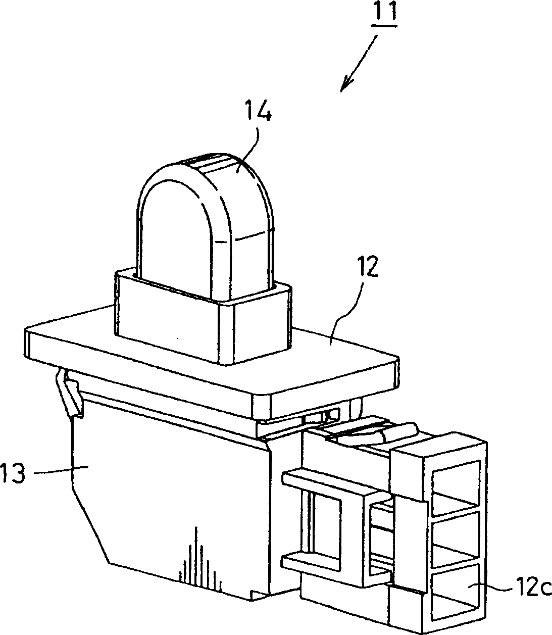
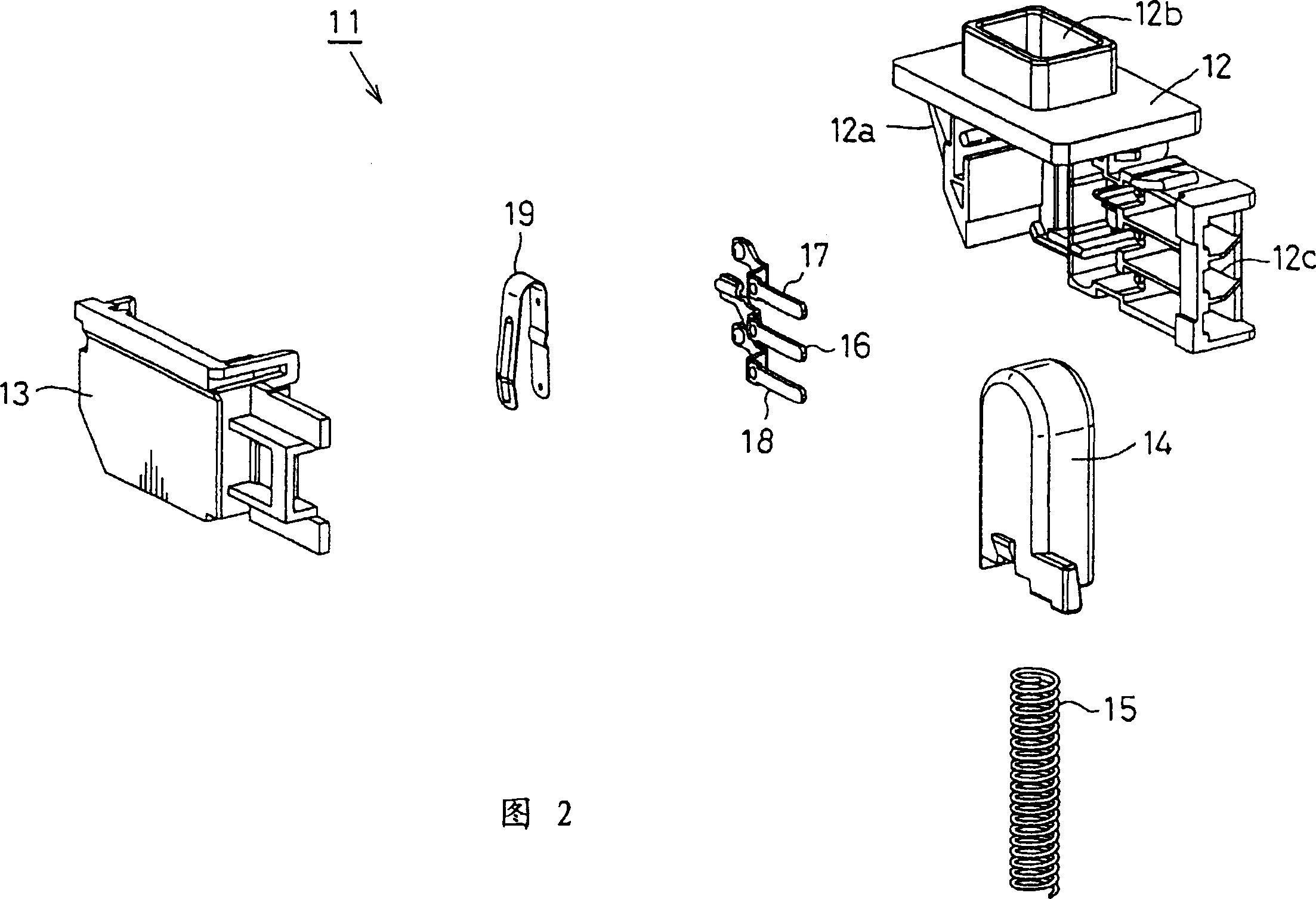
[0084] The attached picture shows a push button switch for refrigerator door opening and closing, in figure 1 As shown in FIG. 2 , the push button switch 11 is composed of a housing 12 , a cover 13 , a button 14 , a return spring 15 , three fixed terminals 16 to 18 and a movable piece 19 .

[0085] The housing 12 has an attachment cavity in which the above-mentioned components are assembled, and the cavity is closed by a cover 13 which will be described later.

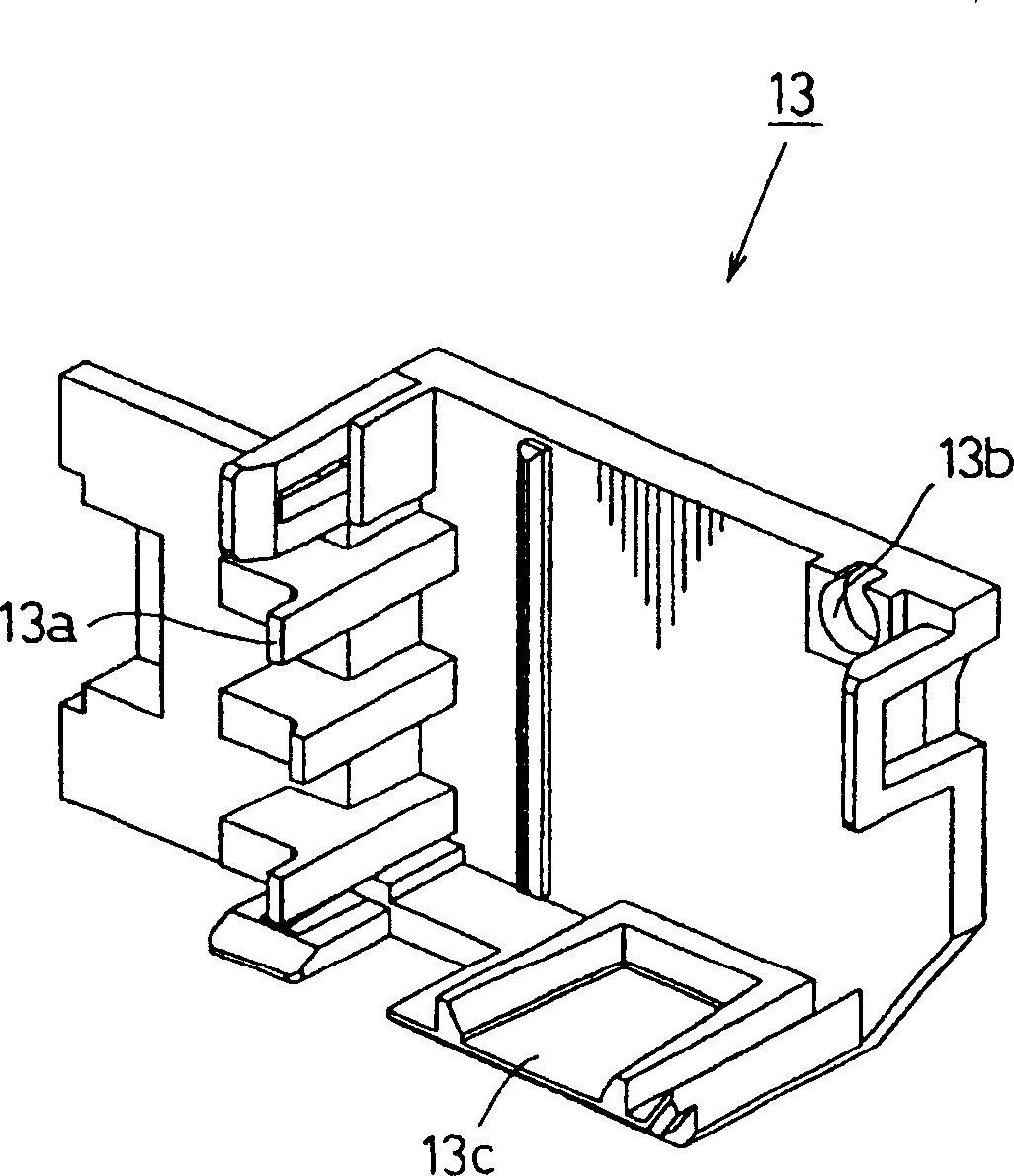
[0086] image 3 The cover 13 is shown, and the cover 13 is installed from a side opening 12a (refer to FIG. 2 ) of the casing 12, and the inner surface of the cover 13 has fixed terminals 16 to 18 and movable terminals respectively divided and supported to be described later. Partition member 13a of sheet 19.

[0087] On the upper side of the cover 13, there is a shaft support portion 13b that realizes the common use of rotary switches of different specifications. This type of cover 13 can be used for push-button swi...

no. 2 Embodiment

[0111] Hereinafter, instead of the push-button switch 11, a case where a rotary switch is similarly used as a refrigerator door switch will be described.

[0112] Figure 14 with Figure 15 Among them, the rotary switch 141 is formed by integrally assembling the housing 142, the cover 143, the rotary joystick 144, the return spring 145, the three fixed terminals 146-148, and the movable piece 149.

[0113] The housing 142 has a hollow portion for fitting the components described above, and the hollow portion is closed by a cover 143 which will be described later.

[0114] The cover 143 and image 3 The illustrated cover 13 is the same as the push button switch 11, and is integrally attached from one side opening 142a of the housing 142. As shown in FIG.

[0115] Figure 16 Represents the rotating joystick 144, the rotating joystick 144 has a fan shape, along its inclined upper surface, a joystick pressing piece 144a is extended obliquely upward, and a supporting shaft 144b...

no. 3 Embodiment

[0150] Figure 27 And Fig. 28 represents another kind of button switch 271 that is used for refrigerator door switch, and the feature of this button switch 271 is to be provided with the housing 272 that can be used in common for multiple button switches, is housing 272, cover 273, button 274, back-moving spring 275, 3 fixed terminals 276~278, movable piece 279 carry out integral assembly and constitute.

[0151] Figure 29 The housing 272 is shown, and the housing 272 has a hollow part for assembling the components described above, and a push button 274, a return spring 275, three fixed terminals 276 to 278, As for the movable piece 279, the one side opening 272a is closed by a cover 273 which will be described later.

[0152] On the upper surface of the housing 272, there is a cylindrical portion 272b penetrating in the vertical direction. Here, the push button 274 is slidably inserted in the vertical direction. At a position adjacent to the inner side of the button 274, ...


PUM


Abstract

The present invention is provided with a contact switching mechanism having a movable contact member that is bent into a U shape, allowed to press and contact a fixed contact member side, and supported so as to freely tilt and move thereon. In this mechanism, a switching operation is carried out between contacts by reversing the movable contact member in a see-saw manner, with a tilt-movement fulcrum portion of the movable contact member being always in contact with the contact portion of the common fixed contact member. The movable contact member is allowed to have a spring function conformed to elastically shift in response to a switching operation in addition to a contact function that is inherent to the movable contact member so that it is possible to provide a switch having high reliability, such as a push-button switch and a rotary-lever switch, which can cut costs by reducing the number of parts, and ensure a superior contacting property.

Description

technical field [0001] The present invention relates to a switch for a door switch of a refrigerator, and more particularly, to a switch, a push button switch and a rotary switch capable of achieving reduced number of parts and stable contact performance. Background technique [0002] Generally speaking, a switch used in household appliances, such as a switch assembled on a household refrigerator, also has the switch function of turning on and off the electric light in the refrigerator and turning on and off the cooling motor when opening and closing the refrigerator door. [0003] As a necessary condition of the door switch, when the door switch is installed on a household refrigerator, due to the dimensional error between the shape of the door switch itself and the shape of the recessed part of the refrigerator installation position, the protrusion amount of the operation part (actuator) for the push operation is different. Therefore, the operation It is difficult to ensur...

Claims


Application Information

Patent Timeline
Patent Type & Authority Patents(China)
IPC IPC(8): H01H13/08H01H13/18H01H1/26H01H15/10H01H21/28
CPCH01H13/183H01H1/26H01H15/102H01H21/282
Inventor 清野泰弘鸣尾俊博
Owner ORMON CORP
Why Eureka
Try Eureka