Check patentability & draft patents in minutes with Patsnap Eureka AI!

Electric tool

A technology for electrical appliances and electrical switches, which is applied to electrical components, circuits, electrical switches, etc., can solve the problem of the limitation of the freedom of switch component layout, and achieve the effect of simple wiring

Inactive Publication Date: 2007-01-24
MARQUARDT GMBH SCHLOSSTRASSE 16 7201 RIETHEIM-WEILHEIM 1 WEST GERMANY
View PDF3 Cites 0 Cited by
  • Summary
  • Abstract
  • Description
  • Claims
  • Application Information

AI Technical Summary

Problems solved by technology

However, since the rod is rigid, the freedom of arrangement of the switch components within the power tool housing is greatly restricted

Method used


Image

  • Electric tool
  • Electric tool
  • Electric tool

Examples


Embodiment Construction

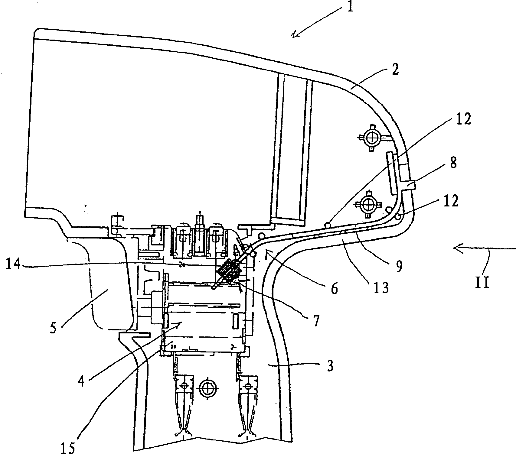
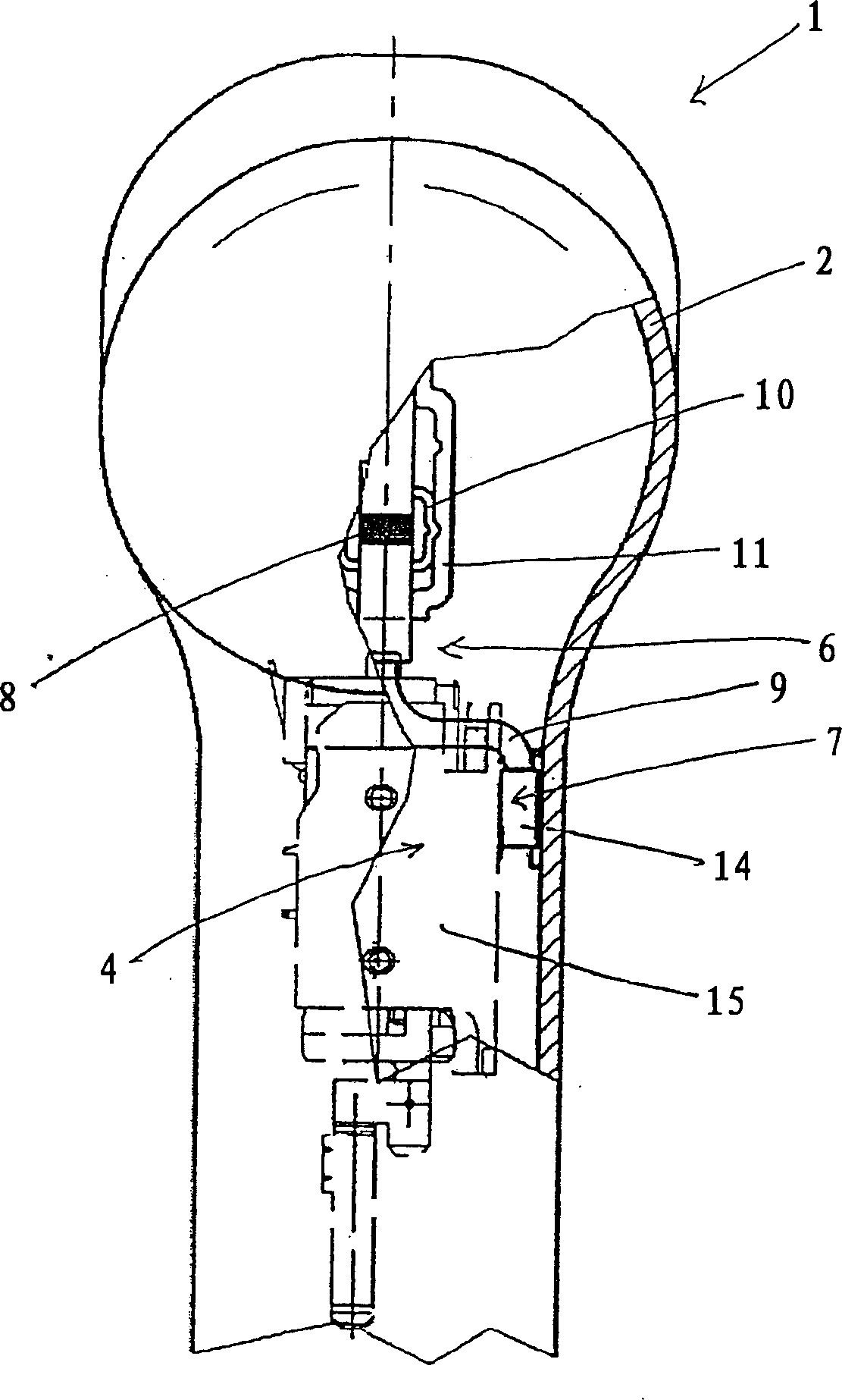
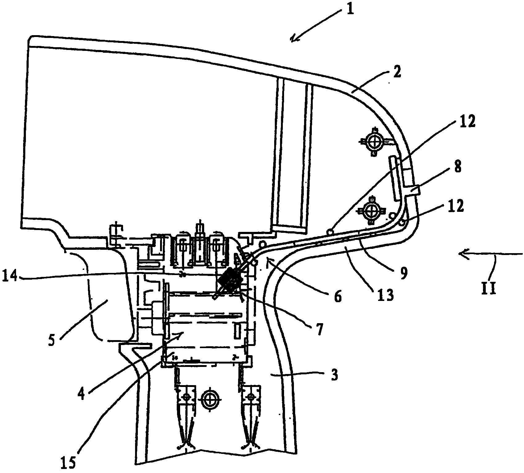
[0017] in figure 1 The hand-operated electric tool 1 shown in the figure can be a drill, an electric screwdriver, a battery-driven screwdriver, a curved hand grinder, etc. It has a housing 2 and a handle 3. In the housing 2, more specifically, in the handle 3 of the housing 2, an electric switch 4 for turning on and off the hand-operated electric tool 1 is installed. To this end, the switch 4 has an operating mechanism 5 that can be moved manually by the operator. When necessary, the manual electric tool 1 may be equipped with an electronic device for controlling the rotation speed, so that the operator can adjust the rotation speed according to the position of the operating mechanism 5. The electronic device is suitably located in the switch housing 15 of the switch 4.

[0018] The electric hand tool 1 additionally has a switching device 6 which is used, for example, to activate the pulse function of the electric hand tool 1. When operating with the pulse function turned on, the...


PUM


Abstract

The invention relates to an electric switch mechanism (6), in particular for an electric hand tool (1), such as a drill, an electric screwdriver, an angle grinder or similar. Said mechanism comprises a switch element, which is not accessible to the user (7), in addition to an actuating element (8) for actuating the switch element (7), which is accessible to said user. The actuating element (8) is located at a distance from the switch element (7) and a plastic element (9) is positioned between the actuating element (8) and the switch element (7), in such a way that the force exerted by the user on the actuating element (8) can be transmitted to the switch element (7) via said plastic element (9).

Description

Technical field [0001] The invention relates to an electrical appliance. Background technique [0002] Such electrical appliances can be drills, electric screwdrivers, such as battery-driven screwdrivers, hand-held grinders, and other hand-operated electric tools. [0003] The electric tool has a shell with a handle, and an electric switch with a manual operation mechanism is installed in the shell, which is used to turn on and turn off the manual electric tool. When necessary, the speed of the electric tool can be adjusted according to the position of the operating mechanism. If the user of the hand-operated electric tool is to be able to adjust other functions, such as the pulse function with impact rotation of the tool mounting head used for screwing, there is a switch part in the housing for this purpose. Operating parts for manually turning on and off these other functions are provided in this switch part. Because the switch part is located in the housing of the electric too...

Claims


Application Information

Patent Timeline
Patent Type & Authority Patents(China)
IPC IPC(8): H01H9/06H01H3/38
CPCH01H3/38B25F5/00H01H9/06
Inventor 彼得·布罗格哈默赖纳·比施勒
Owner MARQUARDT GMBH SCHLOSSTRASSE 16 7201 RIETHEIM-WEILHEIM 1 WEST GERMANY
Features
  • R&D
  • Intellectual Property
  • Life Sciences
  • Materials
  • Tech Scout
  • Unparalleled Data Quality
  • Higher Quality Content
  • 60% Fewer Hallucinations
Learn More