Motor controlling device
A technology of motor control and motor position, applied in the direction of electrical program control, motor speed or torque control, control system, etc., to achieve the effect of improving the accuracy of the actual trajectory
- Summary
- Abstract
- Description
- Claims
- Application Information
AI Technical Summary
Problems solved by technology
Method used
Image

Examples
specific Embodiment approach 1
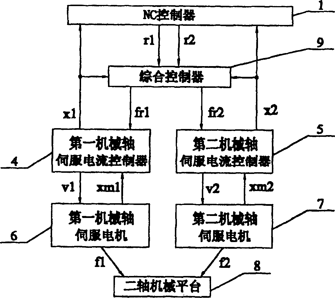
[0066] Specific implementation plan one: the following combination figure 1 This embodiment will be specifically described. It is generated according to the first torque command fr1 and the first motor position xm1 by the NC controller 1 with the ability to generate the first NC position command r1 and the second NC position command r2 and monitor the first position feedback x1 and the second position feedback x2 The first mechanical axis servo current controller 4 of the first power signal V1 and the first position feedback x1 generates the second power signal V2 and the second position feedback x2 according to the second torque command fr2 and the second motor position xm2 The mechanical axis servo current controller 5 generates the first mechanical drive power f1 according to the above-mentioned first electric power signal V1 and provides the first mechanical axis servo motor 6 with the first motor position xm1, and generates the second mechanical drive according to the ab...
specific Embodiment approach 2
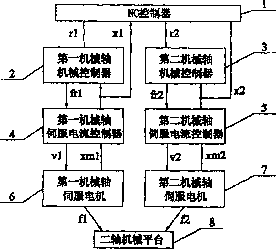
[0070] Specific implementation scheme two: combine below image 3 This embodiment will be described in detail. It consists of an NC controller 1 that generates the first NC position command r1 and the second NC position command r2 and monitors the first position feedback x1 and the second position feedback x2, and generates the second position command according to the first power signal V1. A first mechanical axis servo motor 6 with mechanical driving power f1 and providing the first motor position xm1, a second mechanical axis servo motor 7 generating the second mechanical driving power f2 and providing the second motor position xm2 according to the second electric signal V2, The two-axis mechanical platform 8 that generates mechanical motion under the action of the first mechanical driving power f1 and the second mechanical driving power f2, according to the above-mentioned first NC position command r1, second NC position command r2, first position feedback x1 and second Thr...
specific Embodiment approach 3
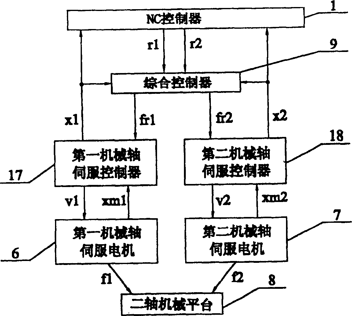
[0071] Specific implementation scheme three: the following combination Figure 8 This embodiment will be specifically described. The difference between this embodiment and Embodiment 1 or 2 is that the integrated controller 9 in the motor control device includes: generating the first real-time position command rt1 and the second NC position command r2 according to the above-mentioned first NC position command r1 The command restorer 10 of the second real-time position command rt2; according to the first real-time position command rt1, the second real-time position command rt2, the first position feedback x1, and the second position feedback x2, the first real-time acceleration command ft1 is generated, and the second real-time acceleration command ft1 is generated. Two-axis mechanical controller 11 for real-time acceleration command ft2; command distributor 12 for generating first real-time acceleration command ft1, second real-time acceleration command ft2, first torque comma...
PUM
 Abstract
Description
Claims
Application Information
 - R&D Engineer
- R&D Manager
- IP Professional
- Industry Leading Data Capabilities
- Powerful AI technology
- Patent DNA Extraction
Browse by: Latest US Patents, China's latest patents, Technical Efficacy Thesaurus, Application Domain, Technology Topic.
© 2024 PatSnap. All rights reserved.Legal|Privacy policy|Modern Slavery Act Transparency Statement|Sitemap