
Mobile radio terminal

A mobile wireless and terminal technology, applied in the direction of antenna, radio/inductive link selection arrangement, folding antenna, etc., can solve the problems of antenna resistance characteristics and radiation characteristics changes, etc.

Inactive Publication Date: 2007-02-07
LENOVO INNOVATIONS LTD HONG KONG
View PDF5 Cites 0 Cited by
  • Summary
  • Abstract
  • Description
  • Claims
  • Application Information

AI Technical Summary

Problems solved by technology

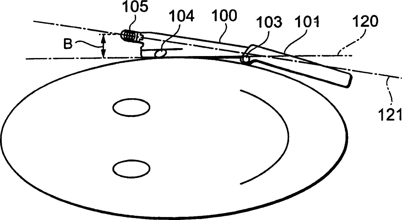
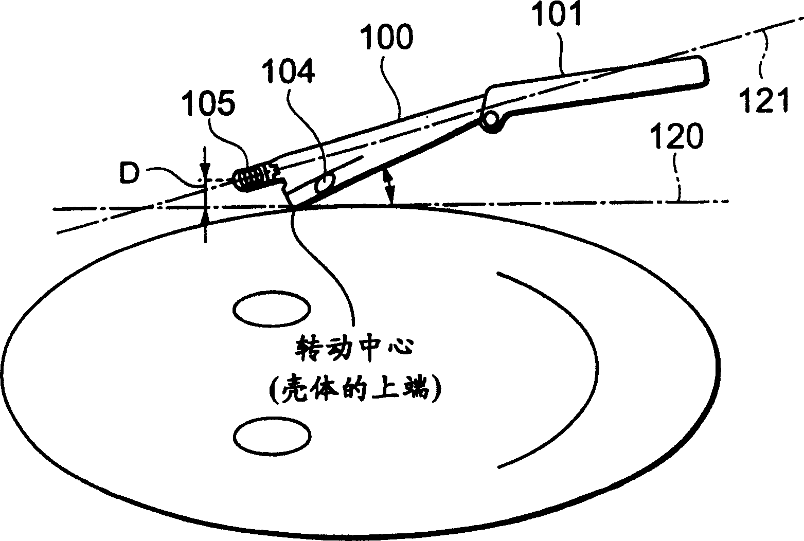
[0006] However, when the housing rotated around the upper end 106 of the upper housing 100 on the cheek contact side, the inner surface of the upper housing 100 moved away from the cheek, as shown in Figure 2, the distance between the antenna tip 105 and the head (D

Method used


Image

  • Mobile radio terminal
  • Mobile radio terminal
  • Mobile radio terminal

Examples


Embodiment Construction

[0023] Embodiments of the present invention will be described in detail below with reference to the accompanying drawings.

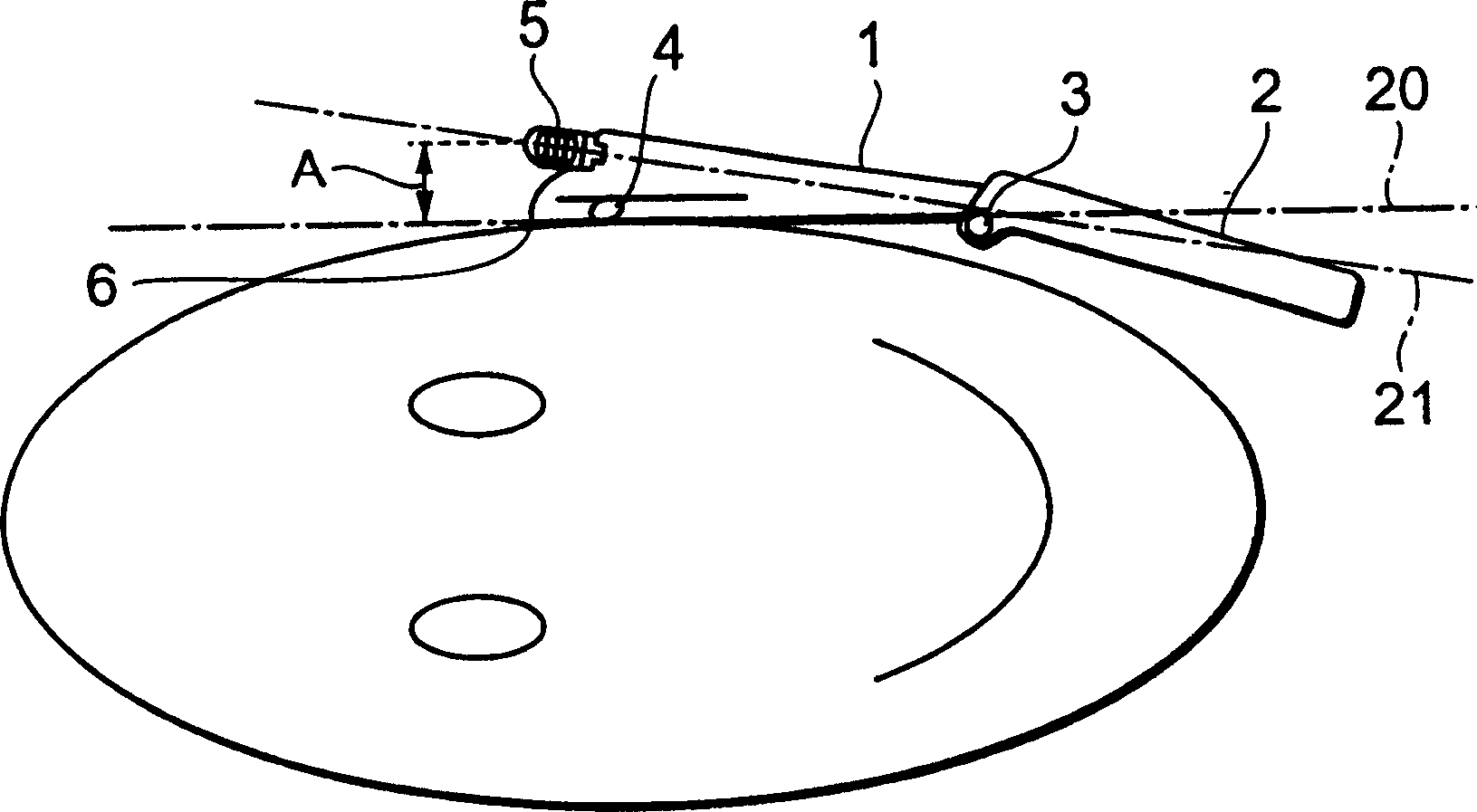
[0024] image 3 and Figure 4 A front view of a mobile radio terminal according to a first embodiment of the present invention is shown, in a position where a call is in progress. Referring to the drawings, a mobile wireless terminal in a first embodiment mode of the present invention has an upper case 1 provided with a receiving portion 4, and a lower case 2, which are rotatably connected together by a hinge portion 3. The mobile radio terminal is preferably a mobile telephone terminal capable of mobile communication.

[0025] The upper case 1 accommodates an extendable antenna, which can be pulled out from the case, and whose top 5 protrudes from the upper end of the upper case 1 . The antenna top 5 has the top of the antenna element (or the helical coil part, hereinafter simply referred to as the coil part) inside. image 3 and Figure 4 The tangen...


PUM


Abstract

There is provided a mobile wireless terminal permitting the distance between the antenna and the human head can be kept relatively constant even if the angle formed by the case of the apparatus is varied, making it possible to ensure stable antenna performance. A mobile wireless terminal according to the invention is fitted to an upper case and has an antenna extensible from the upper case and, when that antenna is stowed in the upper case, the upper end of the upper case protrudes farther than the position of an 1 / 2 length of a coil section, which is the tip section of an antenna element positioned at the tip section of the antenna.

Description

technical field [0001] The present invention relates to a mobile wireless terminal provided with an antenna device extendable from a housing of the mobile wireless terminal, and more particularly, to an improvement in the antenna device which prevents degradation of the antenna performance. Background technique [0002] Mobile wireless terminals capable of mobile communication are usually very sensitive to wide fluctuations in electromagnetic wave conditions during handover, and require stable antenna performance to ensure stable wireless characteristics. Especially when communicating close to the human body, when the antenna is very close to the human head, it is prone to loss, and the performance of the antenna is greatly reduced due to the human head. When the antenna is retracted, it is closer to the person's head than when it is extended, so its performance is very prone to degradation due to proximity to the head. [0003] In addition, since the angle formed by the ho...

Claims


Application Information

Patent Timeline
Patent Type & Authority Patents(China)
IPC IPC(8): H04M1/02H04Q7/32H01Q1/10H01Q1/24H04B1/38
CPCH01Q1/244H04B1/3838H01Q1/245
Inventor 原野信也
Owner LENOVO INNOVATIONS LTD HONG KONG
Learn More