Backlight modular

A backlight module and light guide plate technology, applied in optics, nonlinear optics, instruments, etc., can solve problems such as not conforming to environmental protection trends, CCFL damage, shortening, etc.

Inactive Publication Date: 2007-02-21
AU OPTRONICS CORP
View PDF7 Cites 1 Cited by
  • Summary
  • Abstract
  • Description
  • Claims
  • Application Information

AI Technical Summary

Problems solved by technology

The disadvantage of using CCFL as a light source is that the lamp tube contains mercury vapor, which does not meet the future environmental protection trend
In addition, due to the slender tubular structure of CCFL, CCFL is easily damaged by external impact during transportation, which increases the risk of shortening the life of CCFL
In addition, if one of the lamps ages faster, uneven luminance will appear immediately, greatly affecting the brightness quality of the backlight module.

Method used


Image

  • Backlight modular
  • Backlight modular
  • Backlight modular

Examples


no. 1 example

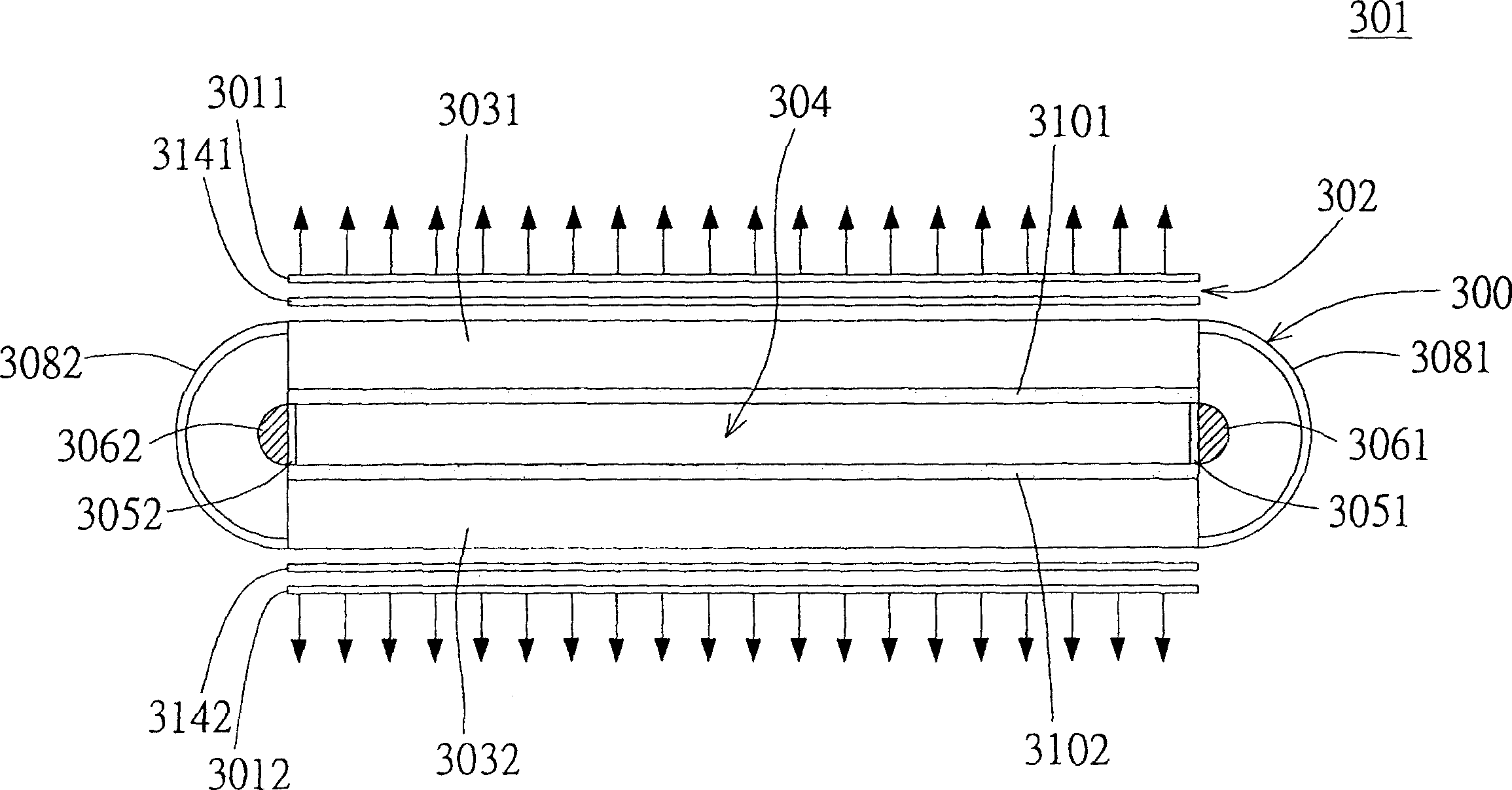
[0041] Please refer to Figure 3A , which shows a cross-sectional view of the backlight module according to the first embodiment of the present invention. exist Figure 3A Among them, the backlight module 300 is suitable for a double-sided display 301. The double-sided display 301 has two display panels 3011 and 3012 arranged flat to each other. A panel gap (gap) space 302 is formed between the display panels 3011 and 3012. The backlight module 300 is disposed in the panel gap space 302 to provide the light required by the double-sided display 301 .

[0042] The backlight module 300 includes at least a first light guide plate 3031 , a second light guide plate 3032 , a first circuit board 3051 and at least one first light emitting diode (LED) 3061 . The first light guide plate 3031 and the second light guide plate 3032 are both arranged in the panel gap space 302 and parallel to the display panel 3011 and the display panel 3012, and a light guide plate gap is formed between t...

no. 2 example

[0049] Please refer to Figure 4 , which shows a cross-sectional view of the backlight module according to the second embodiment of the present invention. exist Figure 4 Among them, the difference between the double-sided display 401 and the double-sided display of the first embodiment lies in the backlight module 400, and the difference between the backlight module 400 of this embodiment and the backlight module 300 of the first embodiment lies in the structure of the curved reflector , and the same symbols are used for the rest of the same constituent elements, and will not be repeated here.

[0050] The center of the concave surface of the first curved reflector 4021 has a first convex surface 4041 , and the first convex surface 4041 faces the first LED 3061 . Likewise, the center of the concave surface of the second curved reflector 4022 has a second convex surface 4042 , and the second convex surface 4042 faces the second LED 3062 . Through the design of the first con...


PUM


Abstract

Double-sided display possesses two parallel display panels. A panel gap space is formed between two display panels. Back light module includes two light guiding plates, a circuit board and at least light-emitting diode. The two light guiding plates parallel to two display panels are setup in the panel gap space. A light guiding plate gap space is formed between two light guiding plates. The circuit board is in the light guiding plate gap space at two sides position. Light-emitting diodes connected to the circuit board are extended out of the light guiding plates.

Description

technical field [0001] The present invention relates to a backlight module, in particular to a backlight module configured in a double-sided display and using a light emitting diode (LED) as a light source. Background technique [0002] Please refer to figure 1 , which shows a cross-sectional view of a traditional unidirectional light emitting backlight module. The unidirectional backlight module 100 mainly includes a light guide plate 106, two cold cathode fluorescent lamps (Cold Cathode Fluorescent Lamp, CCFL) 102, two lamp reflectors (lamp reflector) 104, and a reflective plate (reflecting plate) 108. . Since the periphery of each cold cathode lamp 102 is surrounded by a lamp reflector 104, the light provided by each cold cathode lamp 102 will be reflected by the corresponding lamp reflector 104 and enter through the two sides of the light guide plate 106. In the light guide plate 106 . The light guide plate 106 guides the received light to evenly scatter (scatter) to...

Claims


Application Information

Patent Timeline
Patent Type & Authority Patents(China)
IPC IPC(8): G02F1/1335
Inventor 周信宏
Owner AU OPTRONICS CORP
Why Eureka
Try Eureka