Steam compression type refrigeration cycle device of approximate ideal inverse Carnot cycle efficiency

A reverse Carnot cycle and refrigeration cycle technology, applied in the field of vapor compression refrigeration cycle devices, can solve the problems of low cycle energy efficiency and large compressor heat load, and achieve the effect of small changes in thermal perfection and high energy efficiency

Inactive Publication Date: 2007-03-14
RESEARCH INSTITUTE OF TSINGHUA UNIVERSITY IN SHENZHEN
View PDF3 Cites 0 Cited by
  • Summary
  • Abstract
  • Description
  • Claims
  • Application Information

AI Technical Summary

Problems solved by technology

[0007] In order to solve the problems of low cycle energy efficiency and large heat load of the compressor in the traditional vapor compression refrigeration cycle system, the present invention provides a vapor compression refrigeration cycle device close to the ideal reverse Carnot cycle efficiency

Method used


Image

  • Steam compression type refrigeration cycle device of approximate ideal inverse Carnot cycle efficiency
  • Steam compression type refrigeration cycle device of approximate ideal inverse Carnot cycle efficiency
  • Steam compression type refrigeration cycle device of approximate ideal inverse Carnot cycle efficiency

Examples


Embodiment Construction

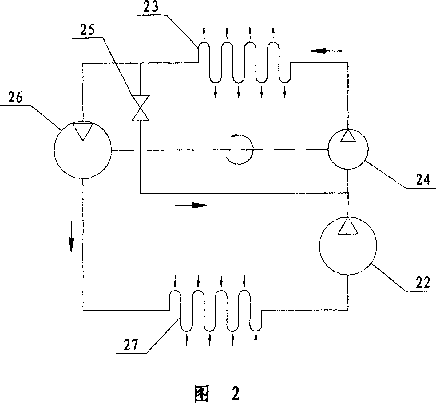
[0029] The vapor compression refrigeration cycle device of the present invention is shown in FIG. 2 . After the outlet of the compressor 22 is connected in parallel with the outlet of the restrictor 25 , it is connected to the inlet of the booster pump 24 . After the inlet of the expansion motor 26 is connected in parallel with the inlet of the restrictor 25, it is connected to the outlet of the condenser 23. The inlet of the evaporator 27 is connected to the outlet of the expansion motor 26 , and the outlet of the evaporator 27 is connected to the inlet of the compressor 22 . The outlet of the booster pump 24 is connected to the inlet of the condenser 23 . The expansion motor 26 is coaxially connected to the booster pump 24 .

[0030] In the refrigeration cycle of the present invention, the isentropic expansion effect of the expansion motor 26 greatly reduces the enthalpy value of the working fluid entering the condenser; the use of the booster pump 24 makes the operating pr...


PUM


Abstract

The steam compressing refrigeration cycle device includes main cycle system comprising booster pump, condensator, expansion motor, evaporator and compressor connected successively with pipeline to output cold; and secondary cycle system comprising throttle connected across the inlet of the booster pump and the outlet of the condensator as well as the booster pump and the condensator, to further lower the temperature of the work medium in the outlet of the compressor. The expansion motor has its output torque rotating the booster pump and has isoentropic expansion to reduce the entropy of the work medium entering the condensator. The booster pump reduces the operation pressure difference and the power consumption of the compressor. Therefore, the present invention has energy efficiency near ideal inverse Carnot cycle and low hot load one compressor, and may be used widely in refrigeration cycle in air conditioner, refrigerator, etc.

Description

technical field [0001] The invention relates to a refrigeration device, in particular to a vapor compression refrigeration cycle device. It is suitable for refrigeration technology fields such as air conditioners and refrigerators. Background technique [0002] The traditional vapor compression refrigeration cycle system is shown in Figure 1. In order to achieve the purpose of refrigeration, compressor 1 is used for adiabatic and isentropic compression, condenser 2 isobaric condensation and heat release, throttle 3 isenthalpic throttling to reduce pressure and temperature, evaporator 4 Thermodynamic cycle process of isobaric endothermic refrigeration. In the figure, the outlet of evaporator 4 is connected to the inlet of compressor 1; the outlet of compressor 1 is connected to the inlet of condenser 2; the outlet of condenser 2 is connected to the inlet of throttle 3; the outlet of throttle 3 is connected to the inlet of evaporator Inlet connection of device 4. [0003] T...

Claims


Application Information

Patent Timeline
Patent Type & Authority Patents(China)
IPC IPC(8): F25B1/00
Inventor 张继恩刘岩冯冠平敬刚吴坚顾墨林
Owner RESEARCH INSTITUTE OF TSINGHUA UNIVERSITY IN SHENZHEN
Why Eureka
Try Eureka