Evaporative cooling type centrifugal chiller and system with same

An evaporative cooling and chiller technology, applied in refrigerators, refrigeration components, compressors, etc., can solve the problems of low energy efficiency, unfriendly surrounding environment, and large loss of circulating water in cooling towers, achieving less power consumption and energy saving. Significant, reduced drift loss effect

Pending Publication Date: 2017-12-19
CHONGQING GENERAL IND (GRP) LTD
View PDF6 Cites 0 Cited by
  • Summary
  • Abstract
  • Description
  • Claims
  • Application Information

AI Technical Summary

Problems solved by technology

The circulating water of the cooling tower has a large drift loss, which is not friendly to the surrounding environment, and the energy efficiency of the water-cooled centrifugal chiller system is low

Method used


Image

  • Evaporative cooling type centrifugal chiller and system with same
  • Evaporative cooling type centrifugal chiller and system with same
  • Evaporative cooling type centrifugal chiller and system with same

Examples


Embodiment 1

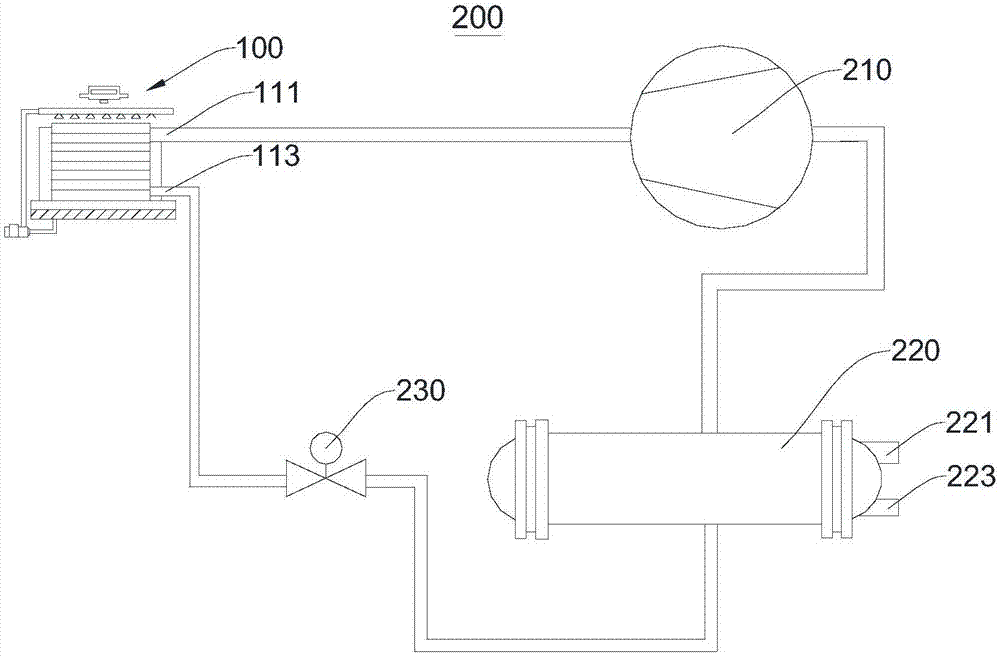
[0034] Please refer to figure 1 and figure 2 , this embodiment provides an evaporative cooling centrifugal chiller 200, including a compressor 210, an evaporative condenser 100, a throttling element 230, and an evaporator 220 connected in sequence, and the evaporator 220 is connected to the compressor 210 to form a refrigeration circuit .

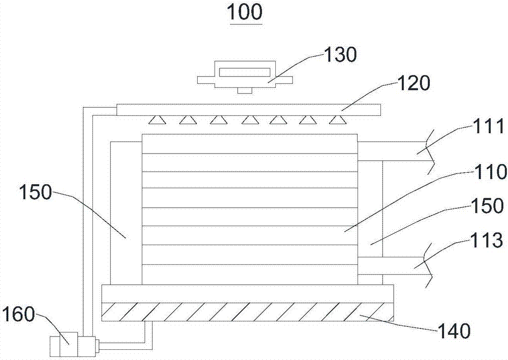
[0035] The evaporative condenser 100 includes a heat exchanger 110 , a water sprayer 120 , a cooling fan 130 , a water receiving tray 140 , a water blocker 150 and a water pump 160 . The water sprayer 120 is disposed on the top of the heat exchanger 110 , that is, above. The cooling fan 130 is disposed on a side of the sprinkler 120 away from the heat exchanger 110 . The water receiving tray 140 is arranged at the bottom of the heat exchanger 110 , and the water blocker 150 is arranged at the left and right sides of the heat exchanger 110 . The water sprayer 120, the water pump 160, the water receiving tray 140 and the heat exchanger 1...

Embodiment 2

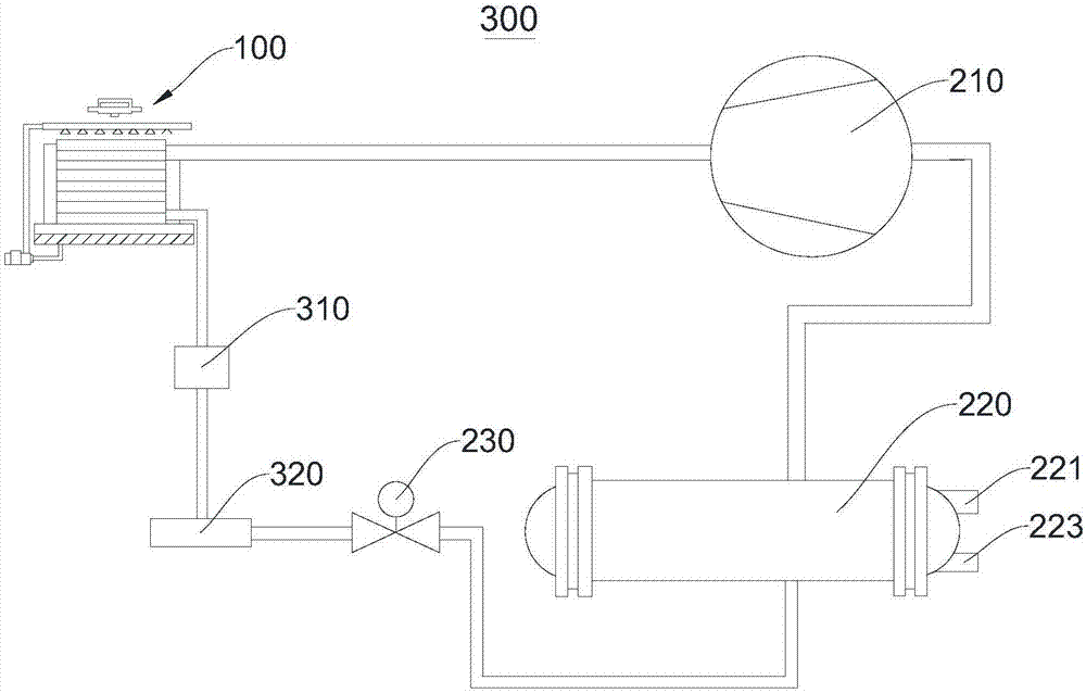
[0046] Please refer to image 3 , this embodiment provides an evaporative cooling centrifugal chiller 300 .

[0047] The difference between the evaporative cooling centrifugal chiller 300 and the evaporative cooling centrifugal chiller 200 mainly lies in:

[0048] The evaporative cooling centrifugal chiller 300 includes an accumulator 310 for storing refrigerant, and the accumulator 310 is respectively connected with the evaporative condenser 100 and the throttling element 230 . The accumulator 310 is configured to receive the refrigerant flowing out of the evaporative condenser 100 and input the refrigerant to the throttling element 230 .

[0049] The evaporative cooling centrifugal chiller 300 also includes a filter 320 for filtering the refrigerant output from the accumulator 310 . When there are impurities and other precipitated substances in the refrigerant, it will affect the normal operation of the evaporative cooling centrifugal chiller 300 . The filter 320 filters o...


PUM


Abstract

The invention provides an evaporative cooling type centrifugal chiller and a system with the same and relates to the technical field of refrigeration. The evaporative cooling type centrifugal chiller comprises a compressor, an evaporative condenser, a throttle element and an evaporator which are sequentially connected, and the evaporator and the compressor are connected to form a refrigeration loop. The structure of the chiller is integrally designed, power consumption is little, the energy efficiency is high, and energy saving and environmental friendliness are achieved. The evaporative cooling type centrifugal chiller system comprises the evaporative cooling type centrifugal chiller. The system is integrally designed, power consumption is little, the energy efficiency is high, and energy saving and environmental friendliness are achieved.

Description

technical field [0001] The invention relates to the technical field of refrigeration, in particular to an evaporative cooling centrifugal chiller and a system thereof. Background technique [0002] The centrifugal chiller uses electricity as the power source. The refrigerant evaporates in the evaporator and absorbs the heat of the refrigerant water for cooling. The refrigerant vapor after evaporation and heat absorption is compressed into a high-temperature and high-pressure gas by the compressor, and condensed by the water-cooled condenser. After that, it becomes a liquid, which is throttled by the expansion valve and enters the evaporator for recirculation. [0003] At present, there are only water-cooled and air-cooled centrifugal chillers on the market. The energy efficiency of the air-cooled centrifugal chiller is low because the system condensing pressure is higher than the ambient dry bulb temperature. The water-cooled centrifugal chiller uses a water-cooled condense...

Claims


Application Information

Patent Timeline
Patent Type & Authority Applications(China)
IPC IPC(8): F25B1/00F25B41/00F25B41/40
CPCF25B1/00F25B41/40
Inventor 何建权温鸿王武平程林
Owner CHONGQING GENERAL IND (GRP) LTD
Why Eureka
Try Eureka