
Leakage gas outlet valve

A technology of gas outlet valve and gas, which is applied in the direction of combustion ignition, combustion method, mechanical ignition, etc., and can solve problems such as fire accidents, slow fire collection, safety defects of gas outlet valves, etc.

Inactive Publication Date: 2007-04-04
许煌熙
View PDF6 Cites 0 Cited by
  • Summary
  • Abstract
  • Description
  • Claims
  • Application Information

AI Technical Summary

Problems solved by technology

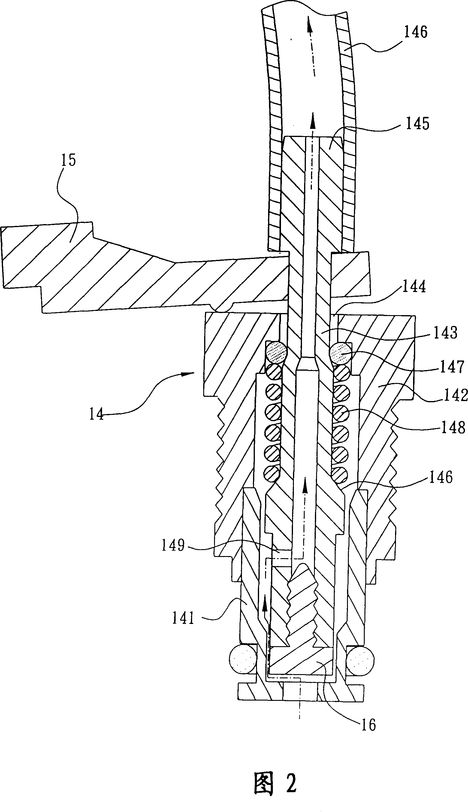
[0005] The above-mentioned pressure igniter manufactured by the gas outlet valve 14 often takes place slowly after being ignited, causing the user to think that the driving piece 15 has been loosened to restore the gas outlet nozzle 143 to its original position, and the gas cylinder 13 The gas inside has blocked the flame and no longer continues to burn, but this is not the case. Please refer to shown in Figure 1. When the driving piece 15 is released, the gas outlet 143 returns to its original position, although the airtight gasket 16 at the bottom of the gas outlet 143 The bottom end of the seat body 141 has been sealed to block the gas in the gas cylinder 13, but the gasket 147 in the front port 144 of the screw sleeve 142 is still in a sealed state due to the support of the spring 148, causing the gas outlet pipe 151 The remaining gas inside cannot flow back due to the principle of pipe flow and pressure, and can only overflow along the gas outlet pipe 151, that is, when the gas pressure in the gas outlet pipe 151 is greater than the external pressure, the gas inside will flow continuously It flows out toward the free end of the pipe body 11, and gradually stops flowing out when the pressure in the outlet pipe 151 is gradually lower than the external pressure.
[0006] In view of the fact that the above-mentioned inventor feels that the gas outlet valve in the traditional igniter has existing safety flaws, which are likely to cause irreparable regrets such as fire accidents, and at the same time this type of product is well received by users, therefore, based on the market and The actual needs of users, and in order to solve the above-mentioned problems, so the inventor has been engaged in this industry for many years, but through long-term hard research and experiments, he finally developed and designed a leakable gas outlet valve of the present invention, in order to be used by the present invention. The ingenuity of the invention can provide a more perfect and higher safety igniter

Method used

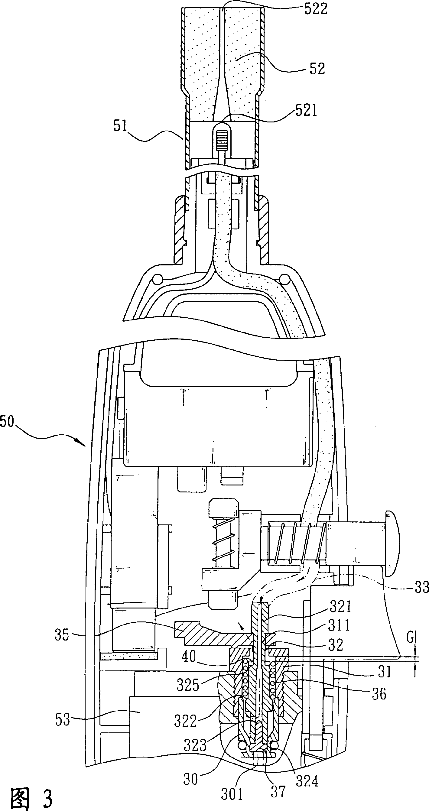

Image

  • Leakage gas outlet valve
  • Leakage gas outlet valve
  • Leakage gas outlet valve

Examples


Embodiment Construction

[0035] In order to facilitate your examiner to have a further understanding and understanding of the technical means and operation process of the present invention, the embodiments are hereby combined with the drawings, and the details are as follows:

[0036] The present invention is a leakable gas outlet valve, which is used in an igniter, which can be a pressure igniter or a general igniter. In this embodiment, please refer to Figure 3, which is an example Take a pressure igniter as an example, which has a slightly rectangular handle 50, one end of the handle 50 extends outward for a certain distance, and a hollow tube 51 is provided, and a pressure head 52 is arranged in the free end of the tube 51. One end 521 of the pressure head 52 has a larger inner diameter at the joint with the pipe body 51, while the inner diameter of the other end 522 is obviously smaller, and a gas cylinder 53 is arranged in the handle portion 50. The gas cylinder 53 one ends are connected with ou...


PUM


Abstract

The invention relates to a leakageable gas out valve used in a spark lighter. The hatch on the bottom base could make the gas coming into it. A screw covering canister is set on the top of the base body, and a gas out rostra extends to the bottom of the hatch. A gas sealed underlay is set at the hatch of the base body. And the hatch is connected to a gas out pipe. A driving piece is set between the hatch out the screw covering canister. A teat is set on a preset length between the inside diameter of the screw covering canister. A shoulder section is set near the hatch of the inside of the screw covering canister, while the shoulder section driving the moving piece pressing, there is a clearance to the hatch of the screw covering canister. Thus, the effect of fast flameout would be realized.

Description

technical field [0001] The present invention relates to a leakable gas outlet valve, especially a gas outlet valve used in an igniter to allow the remaining gas in an outlet pipe to flow backwards and leak to the outside, so that the combustion flame of a fire end of the igniter It can achieve the effect of closing the fire quickly, and the air outlet valve can provide the user with a more complete and higher safety igniter. Background technique [0002] At present, a commonly used pressure igniter is commonly used, as shown in Fig. 1, which has a slightly rectangular handle portion 10, and one end of the handle portion 10 is provided with a hollow pipe body 11 extending outward for a certain distance. A pressure head 12 is arranged in the free end of the pipe body 11. One end 121 of the pressure head 12 has a larger inner diameter at the joint with the pipe body 11, while the inner diameter of the other end 122 is obviously smaller. 10 is provided with a gas cylinder 13, a...

Claims


Application Information

Patent Timeline
IPC IPC(8): F23Q2/16F23Q2/173F23Q1/00
Inventor 许煌熙
Owner 许煌熙
Learn More