Pneumatic continuous needle-free syringe adopting control of pneumatically-controlled slide column valve
A needle-free syringe and valve control technology, applied in the field of syringes, can solve the problems of increased manufacturing cost, inconvenient use, low yield, etc., and achieve the effects of rapid firing, automatic firing, rapid firing, and effective control of yield
- Summary
- Abstract
- Description
- Claims
- Application Information
AI Technical Summary
Problems solved by technology
Method used
Image
Examples
Embodiment 1
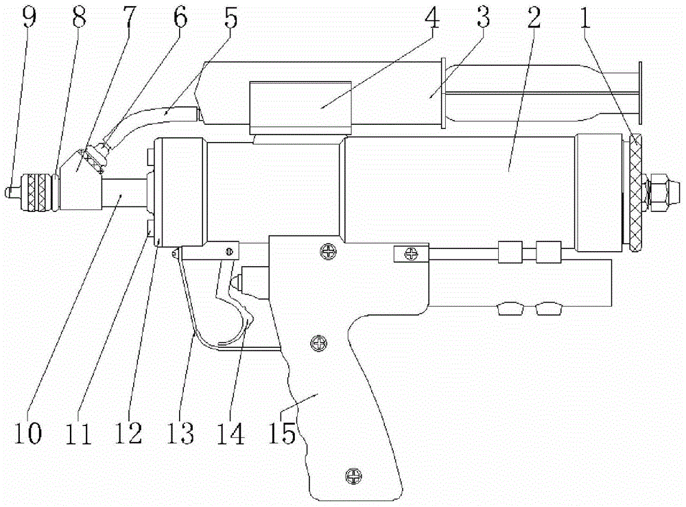
[0063] The pneumatic continuous needle-free injector controlled by the air control spool valve provided in Example 1 has a structure such as Figure 1 to Figure 21 As shown, there is a main body, a pilot valve and an air control spool valve, wherein the main body includes a power source, a liquid medicine storage device, a cylinder block assembly 2, an air storage tank 1, a liquid plunger pump, a microporous jet nozzle 9, and a ring 13 , trigger and handle. Except for the power air source, all other components are integrated and installed on the cylinder block assembly 2 to form an integrated pneumatic continuous needle-free injector controlled by a hand-held air control spool valve.
[0064] The pilot valve is a two-position three-way valve controlled by manpower. Through manual control, its conduction state is changed to inflate or deflate the front end or rear end of No. 1 spool 60 or No. 2 spool 74 . No. 1 pilot valve can be used ( Figure 7 , Figure 14 , Figure 18 )...
Embodiment 2
[0091] The pneumatic continuous needle-free injector controlled by the air-operated spool valve provided in Embodiment 2 is provided with a No. 1 pilot valve, a No. 1 air-operated spool valve, and a main body with the same structure as in Embodiment 1. details as follows:
[0092] See Figure 7 , Figure 14 , Figure 18 , there are internal threads at the front and rear ends of the control valve housing 29, and the internal threads at the rear end of the control valve housing 29 are connected with the external threads of the No. 1 control valve plug screw 65, so that the No. 1 control valve plug screw 65 is installed At the rear end of the valve housing 29, the No. 1 control valve plugging screw 65 is provided with a No. 1 control valve plugging screw air hole 66 which communicates with the atmosphere.
[0093] See Figure 18 , Figure 19 , the No. 1 pilot valve can be composed of: No. 1 pilot valve housing 84, No. 1 pilot valve body 83, No. 1 pilot valve spring 86, No. ...
Embodiment 3
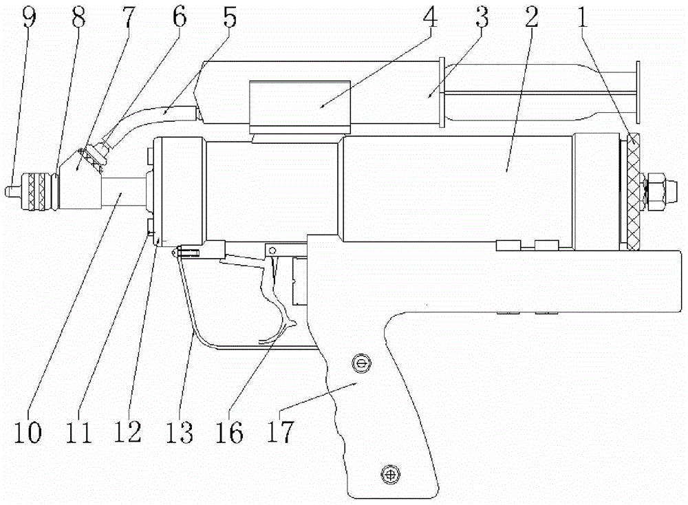
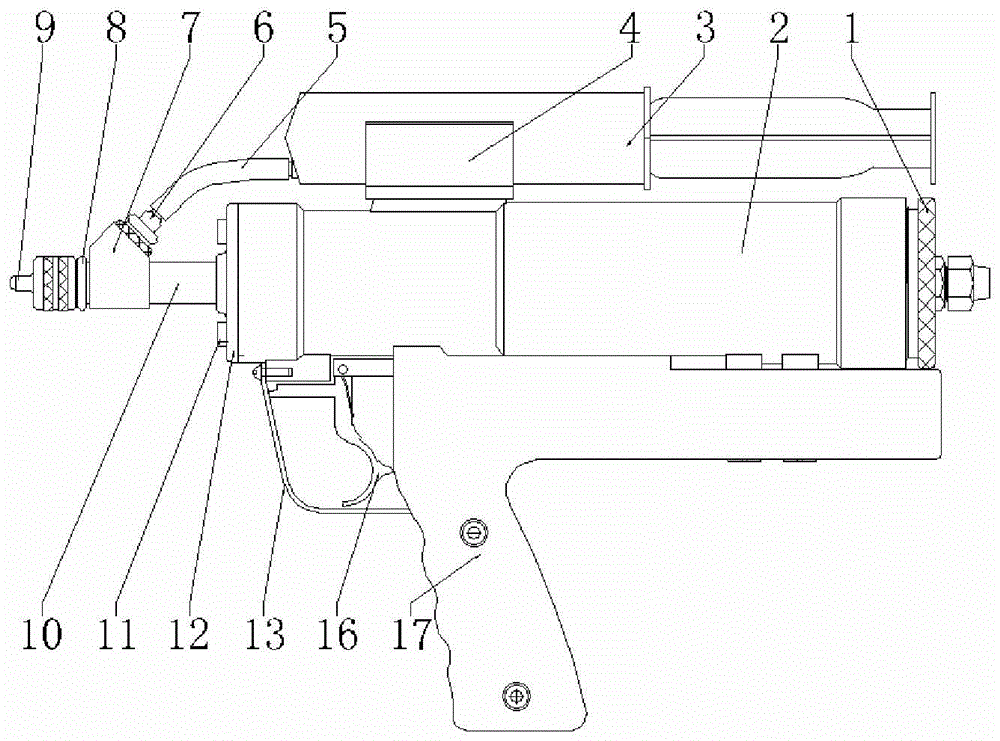
[0128] The pneumatic continuous needle-free injector controlled by the air control spool valve provided in Example 3 is provided with a No. 2 pilot valve, a No. 2 air control spool valve, a No. 2 trigger 16, and a No. 2 handle 17, which are different in structure from that of Example 2. , No. 2 trigger return spring 69, No. 2 handle return spring 78, and other main parts with the same structure as in Embodiment 1. details as follows:
[0129] See Figure 7 , Figure 16 , there are internal threads at the front and rear ends of the control valve housing 29, the internal threads at the front end of the control valve housing 29 are connected with the external threads of the No. 2 control valve plugging screw 71, and the No. sealed.
[0130] See Figure 20 , the No. 2 pilot valve can be composed of: No. 2 pilot valve housing 100, No. 2 pilot valve spring seat 98, No. 2 pilot valve body 104, No. 2 pilot valve spool 109, garden head nut 88, No. 2 pilot valve Pilot valve spring...
PUM
 Abstract
Description
Claims
Application Information
 - R&D
- Intellectual Property
- Life Sciences
- Materials
- Tech Scout
- Unparalleled Data Quality
- Higher Quality Content
- 60% Fewer Hallucinations
Browse by: Latest US Patents, China's latest patents, Technical Efficacy Thesaurus, Application Domain, Technology Topic, Popular Technical Reports.
© 2025 PatSnap. All rights reserved.Legal|Privacy policy|Modern Slavery Act Transparency Statement|Sitemap|About US| Contact US: help@patsnap.com


