Flush valve attachment system

A technique for flushing valves and components, which is applied in the field of flushing valves, can solve problems such as difficulties, and achieve the effects of low production cost, easy installation, and firm assembly

Inactive Publication Date: 2007-04-11
KOHLER CO
View PDF5 Cites 0 Cited by
  • Summary
  • Abstract
  • Description
  • Claims
  • Application Information

AI Technical Summary

Problems solved by technology

This is very difficult because a certain volume of water is required to move quickly through the toilet during flushing and a minimum volume of water needs to be stored

Method used


Image

  • Flush valve attachment system
  • Flush valve attachment system
  • Flush valve attachment system

Examples


Embodiment Construction

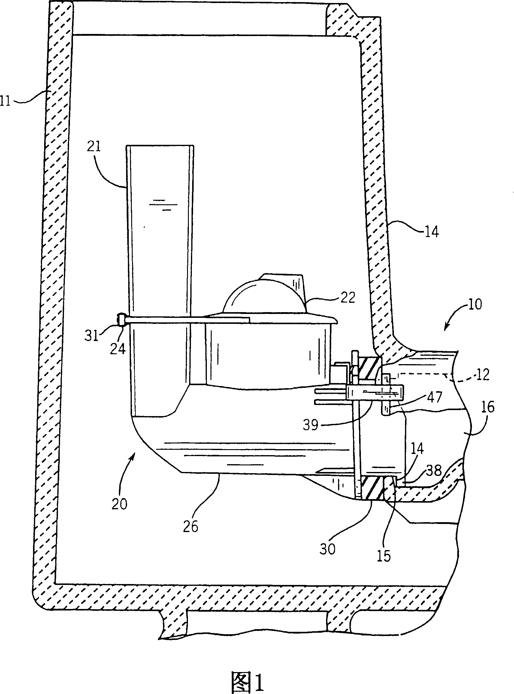
[0021] A one-piece toilet, generally indicated at 10 , includes a tank 11 having a forward substantially vertical wall 14 with an outlet aperture 15 leading to a channel 16 in a conventional toilet rim 12 .

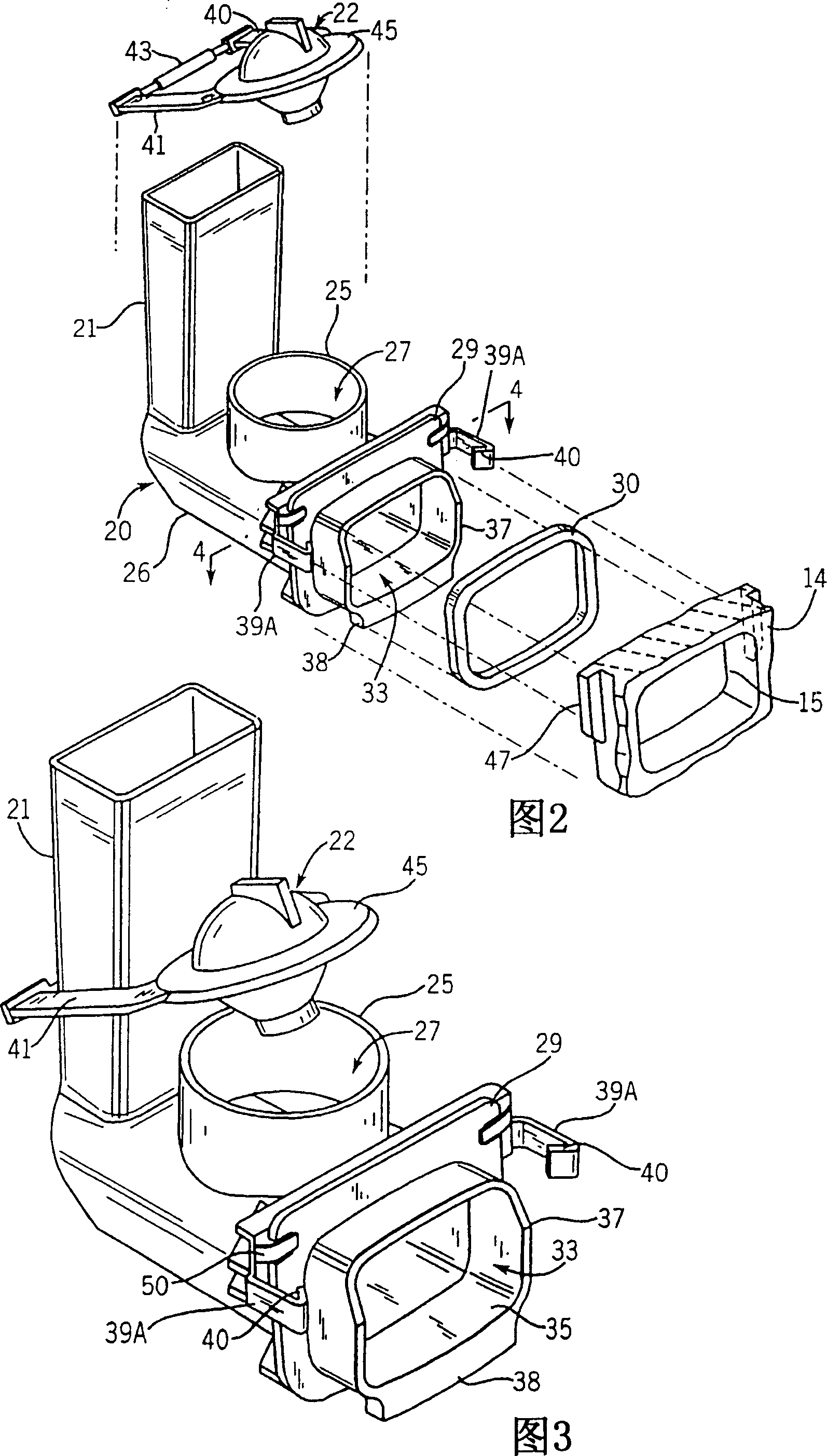
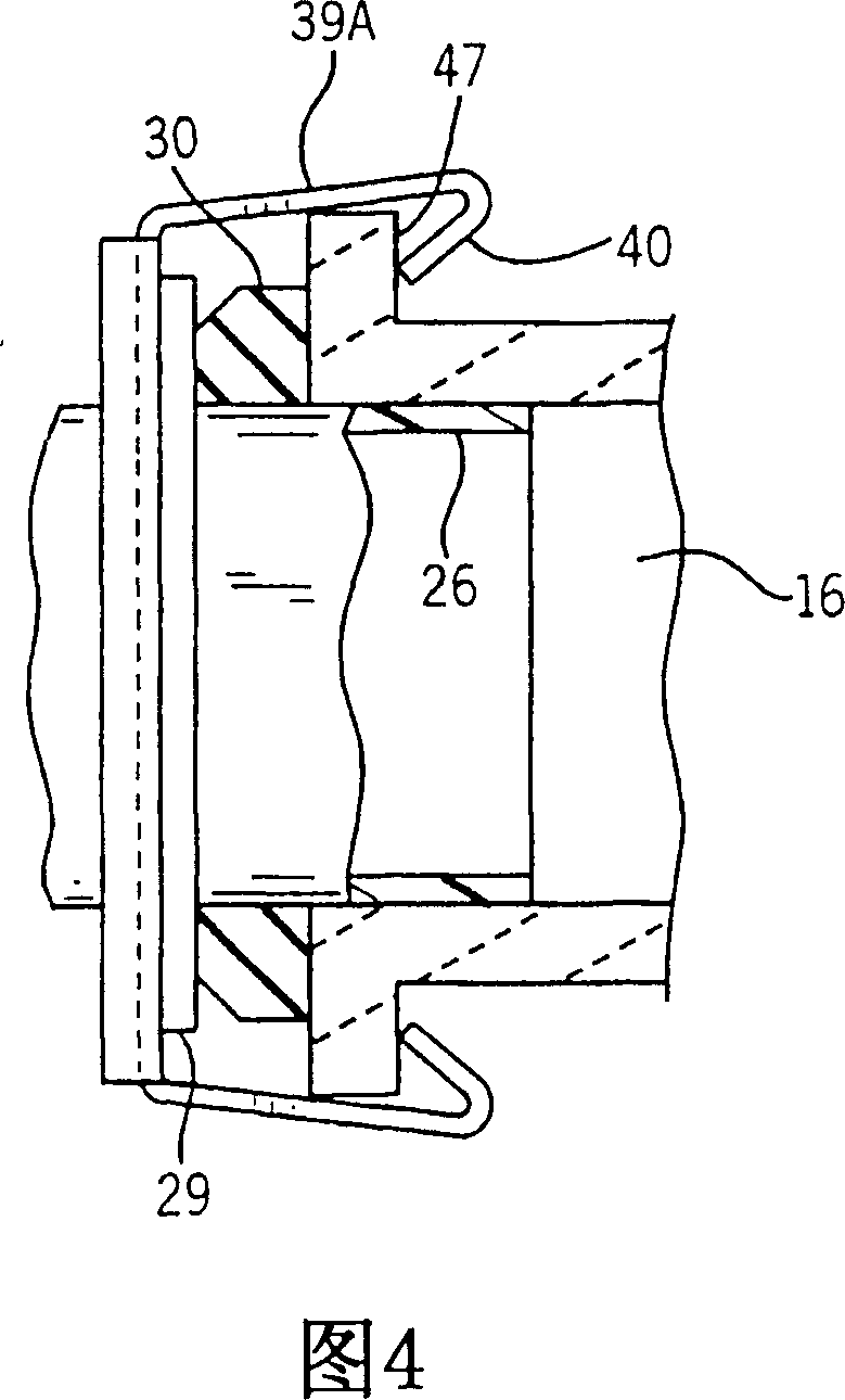
[0022] The flush valve assembly 20 according to the present invention is disposed in the lower portion of the water tank 11 . It has an overflow assembly 21 extending generally vertically. A horizontally extending valve housing 26 passes through the base body of the overflow assembly 21 and defines a channel by which water can be conveyed from the water tank to the channel 16 .

[0023] Regardless of the cross-section of the overflow assembly 21, the cross-section of the housing 26 is a more "flat" cross-section than a simple circular cross-section. For example, the figures show a generally rectangular cross-section with a distance defined by its horizontal walls 35 that is greater than that defined by its vertical walls 37, which still results in a volumetric flow rate ...


PUM


Abstract

A flush valve (20) is connectable to a blind hole (15) in a vertical wall (14) of a toilet tank (11). An overflow member (21) is in fluid communication with a flush valve housing (26). The flush valve housing (26) is wider than it is higher, and fits into a blind hole (15) in the tank wall (14) of similar cross sectional shape. The tank (11) is formed with an attachment ear (47). A clip (39) mounted on the housing (26) holds the housing (26) against the tank wall (14), while the non-circular nature of the housing (26) and blind hold (15) prevent relative rotation there between.

Description

technical field [0001] The invention relates to a flushing valve for controlling water outlet from a toilet water tank. It is especially useful in connection with "monolithic" type low-profile toilets. Background technique [0002] Many toilets are integrally cast with the water tank and the toilet. Hence they are called integral toilets. Due to the adoption of this casting method, it generally cannot reach the bottom wall of its water tank. Usually this is because the channel from the tank to the toilet bowl and / or the toilet siphon riser is cast directly under the tank. With such a toilet, it is difficult to attach a conventional flush valve to the "blind hole" in the bottom of the tank. [0003] In this regard, existing assemblies often clamp the outlet of the valve to the wall by securing a nut on the opposite side of the wall to the outlet end of the flush valve through the bore. It is difficult to place a nut under the bottom wall of the tank and then screw it on ...

Claims


Application Information

Patent Timeline
Patent Type & Authority Patents(China)
IPC IPC(8): E03D1/34E03D1/30
CPCE03D1/306E03D1/34
Inventor D·N·哈洛伦A·H·马茨尼克
Owner KOHLER CO
Why Eureka
Try Eureka