
Hair clipper with improved mounting structures

a mounting structure and clipper technology, applied in the field of clippers, can solve the problems of uncomfortable use of clippers and inability to cut hair smoothly, and achieve the effects of improving mounting structures, improving mounting structures, and improving assembly strength of fixation mounters

Inactive Publication Date: 2008-10-30
JENG SHYUAN PRECISION
View PDF0 Cites 23 Cited by
  • Summary
  • Abstract
  • Description
  • Claims
  • Application Information

AI Technical Summary

Benefits of technology

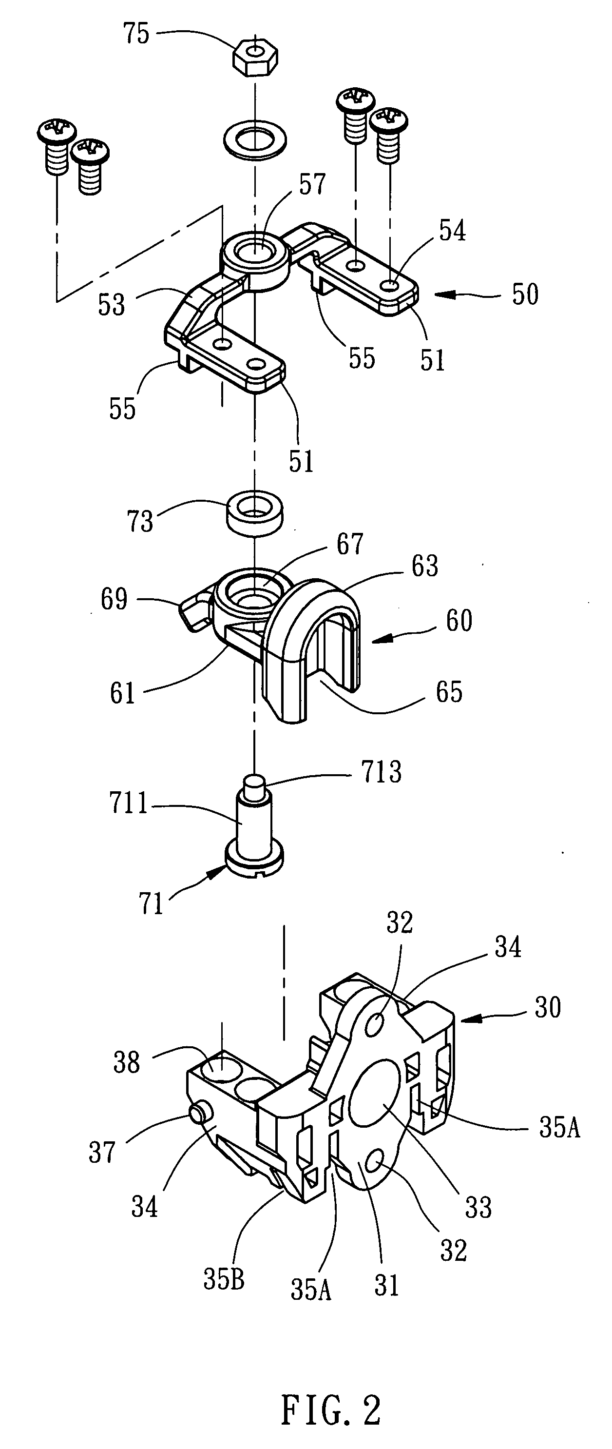
[0006]The present invention has been accomplished under the circumstances in view. The main object of the present invention is to provide an electric hair clipper with improved mounting structures and a fixation mounter is fixed to the motor directly, the fixation mounter further located and positioned to the combination housing, thereby the assembly strength of the fixation mounter is stronger. The sub object of the present invention is to provide an electric hair clipper with improved mounting structures and a bridge of the linking frame is formed of arch shape, and the swiveling leverage is pivoted on the lower end of the bridge of the linking frame, the swiveling leverage can be simplified and reinforced.

Problems solved by technology

Therefore, the vibration of the motor often loosened the mounter from the housing, the position of the swiveling leverage deviated relative to the motor, there also result resonance between the swiveling leverage and the motor, the hair clipper is uncomfortable in use and cannot cutting hair smoothly.

Method used


Image

  • Hair clipper with improved mounting structures
  • Hair clipper with improved mounting structures
  • Hair clipper with improved mounting structures

Examples


Embodiment Construction

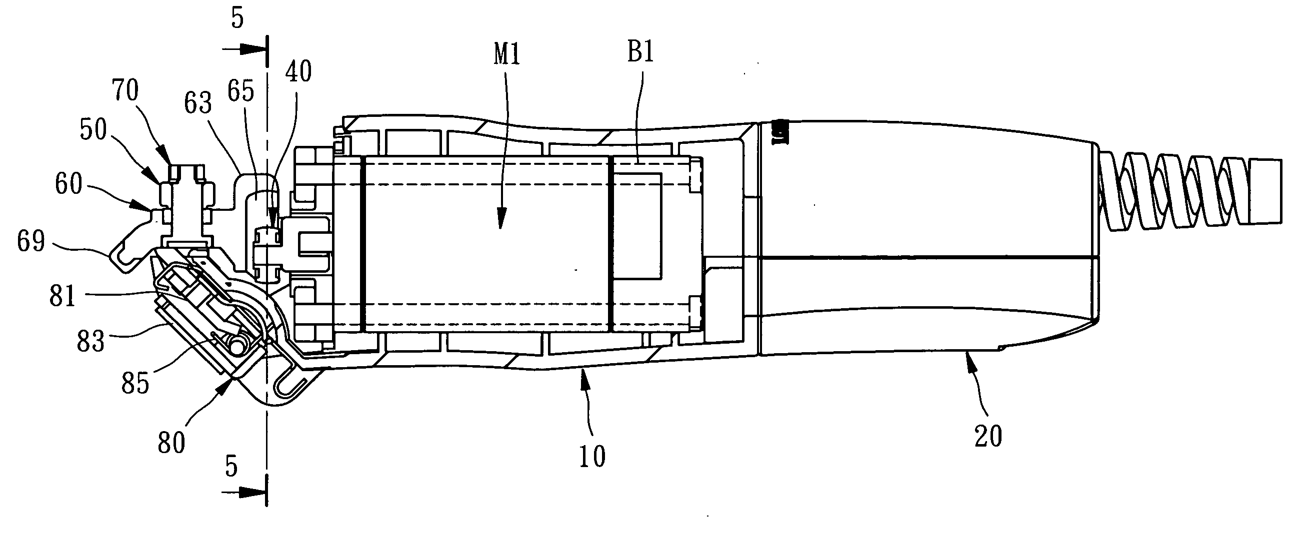
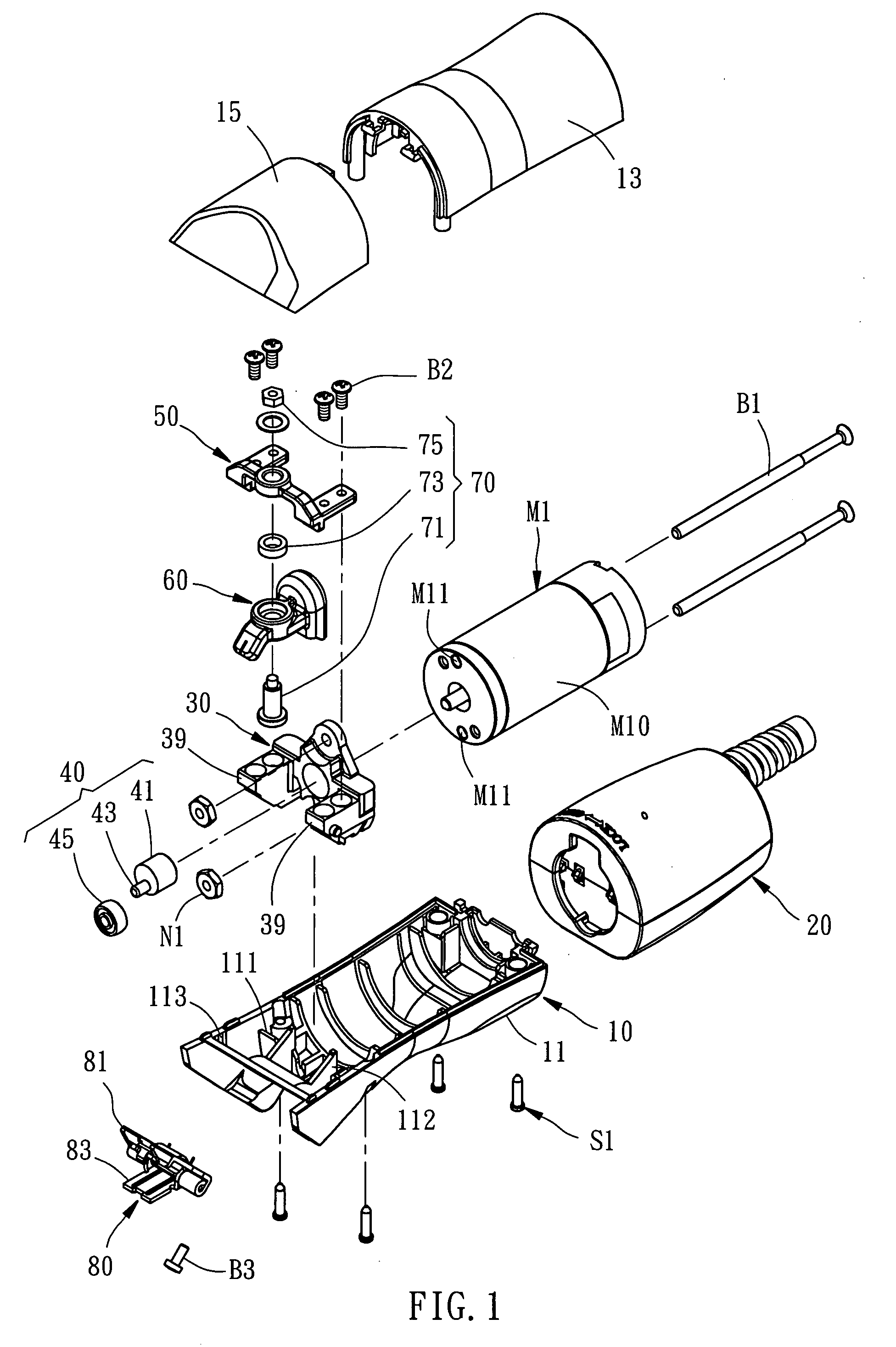
[0018]Referring to the FIGS. 1 to 7, an electric hair clipper with improved mounting structures is used to control the movement of a movable blade C2 of a cutter kit C; the cutter kit C further has a fixed blade C1, and a connect portion C11. The movable blade C2 has a driven portion C21.

[0019]The electric hair clipper comprises the follows.

[0020]A combination housing 10 has a first shell 11, the first shell 11 has two first locating ribs 111 and two second locating ribs 112 perpendicular to the first locating ribs 111, two support sockets 113 is formed at two lateral inner sides of the first shell 11; a second shell 13 and a third shell 15 covered on the first shell 11, and a receiving room formed inside between the first shell 11 and third shell 15. The second shell 13 and third shell 15 further fastened to the first shell 11 via a plurality of screws S1.

[0021]A motor M1 has a motor body M10 being received inside the combination housing 10, two bolting holes M11, a fixing means wh...


PUM


Abstract

An electric hair clipper for adjusting a cutter kit includes a combination housing having a first locating rib and a second locating rib. A motor is received inside the combination housing, the motor has a fixing means, a spindle is provided to rotate. A fixation mounter has a mounting seat fixed by the fixing means, a first locating slot and a second locating slot engaged with the first locating rib and second locating rib of the combination housing respectively. A driving roller set has an impelling roller eccentrically and rotatably connected to the spindle of the motor. A linking frame has two mounter fixing portions, a bridge connects the two mounter fixing portions. A swiveling leverage has a lever body, a driven portion and a blade driving portion connected to each end of the lever body. And a pivot set pivoted to the linking frame and the swiveling leverage.

Description

BACKGROUND OF THE INVENTION[0001]1. Field of the Invention[0002]The present invention relates to a hair clipper and more particularly to an electric hair clipper with improved mounting structures.[0003]2. Description of the Related Art[0004]In prior art, an electric hair clipper that provides a swiveling leverage being pivoted on a linking frame, the swiveling leverage can be driven to a swiveling motion, the linking frame is mounted on a mounter, and the mounter is only fixed to a housing of the hair clipper or formed integral with the housing.[0005]Therefore, the vibration of the motor often loosened the mounter from the housing, the position of the swiveling leverage deviated relative to the motor, there also result resonance between the swiveling leverage and the motor, the hair clipper is uncomfortable in use and cannot cutting hair smoothly.SUMMARY OF THE INVENTION[0006]The present invention has been accomplished under the circumstances in view. The main object of the present ...

Claims


Application Information

Patent Timeline
Patent Type & Authority Applications(United States)
IPC IPC(8): B26B19/00
CPCB26B19/06B26B19/28
Inventor LIAO, YI-TANG
Owner JENG SHYUAN PRECISION
Learn More