Eyepiece system, telescope, binocular and microscope

An eyepiece and positive lens technology, applied in the fields of microscopes, binoculars, and telescopes, can solve the problems of increased processing costs and time-consuming

Inactive Publication Date: 2001-10-10
NIKON CORP
View PDF0 Cites 9 Cited by
  • Summary
  • Abstract
  • Description
  • Claims
  • Application Information

AI Technical Summary

Problems solved by technology

[0007] However, it takes time to form an aspherical shape by fine grindin

Method used


Image

  • Eyepiece system, telescope, binocular and microscope
  • Eyepiece system, telescope, binocular and microscope
  • Eyepiece system, telescope, binocular and microscope

Examples


Embodiment

[0081] Examples of the present invention are described below.

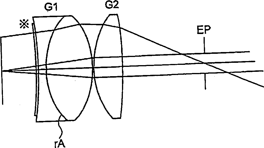
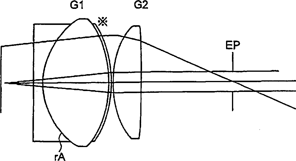
[0082] Each embodiment is composed of a first lens group G1 and a second lens group G2. The first lens group G1 is composed of a negative lens and a positive lens in order from the object side, and the surface on the observer's side is a convex surface facing the observer's side. Moreover, the second lens group G2 is composed of a positive single lens whose surface on the object side is convex toward the object side. At least one lens surface in each lens group is formed in an aspherical shape.

[0083] in addition, figure 1 , image 3 , Figure 5 , Figure 7 , Figure 9 It is the constitution diagram of embodiment 1 to embodiment 5 in sequence. Here, EP in each figure is an exit point, and the surface marked with * indicates an aspherical surface.

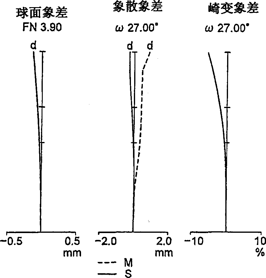
[0084] Tables 1 to 5 below show examples of Examples 1 to 5.

[0085] In each table, No indicates the serial number of the lens surface, R indicates the radiu...


PUM


Abstract

An eyepiece lens system using an aspherical lens can be formed at a low cost, having an eye relief equivalent to 80% or more of the focal length of the entire eyepiece lens system, with aberrations satisfactorily corrected up to the circumference of the field of view, as well as a telescope, a binocular and a microscope. The eyepiece lens system comprises a cemented lens and a positive lens, and at least one of the lens surfaces is formed aspherical. The aspherical surface is a hybrid type spherical surface formed by applying a synthetic resin layer on a basic spherical surface made of glass. There are also provided a telescope, a binocular and a microscope employing such eyepiece lens system.

Description

technical field [0001] The present invention relates to an eyepiece system suitable for observation optical systems such as binoculars, telescopes, and microscopes, and binoculars, telescopes, and microscopes using the eyepiece system. Background technique [0002] The eyepieces used in the observation optical system require a clear field of sufficient length for easy observation of the entire field of view. However, in general eyepiece systems, the shorter the focal length, the greater the sum of the refractive powers of the surfaces constituting the optical system tends to be, resulting in curvature of field aberrations and deteriorating various aberrations. In addition, in the case of a general eyepiece system, the in-focus range is often only as large as about 80% of the focal length. As a result, a sufficient in-focus range cannot be obtained for an eyepiece with a short focal length. [0003] Furthermore, in the case of a general eyepiece system, if the various aberra...

Claims


Application Information

Patent Timeline
IPC IPC(8): G02B25/00
CPCG02B25/001
Inventor 福本哲
Owner NIKON CORP
Why Eureka
Try Eureka