
Car body installation device

A mounting device, the technology of the side mounting part of the body, applied in the connection between the body and the frame, vehicle parts, transportation and packaging, etc., can solve the problem of increasing the number of parts, achieve the reduction of the number of parts, efficient setting operations, damage prevention effect

Inactive Publication Date: 2007-05-30
MITSUBISHI MOTORS CORP
View PDF5 Cites 0 Cited by
  • Summary
  • Abstract
  • Description
  • Claims
  • Application Information

AI Technical Summary

Problems solved by technology

Thus, the number of parts increases

Method used


Image

  • Car body installation device
  • Car body installation device
  • Car body installation device

Examples


no. 1 approach

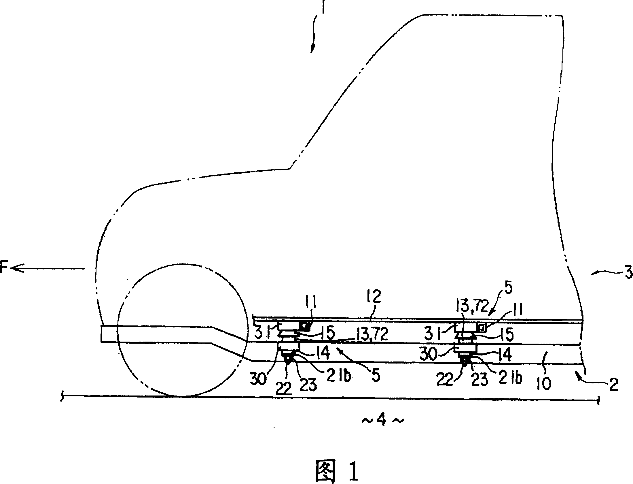
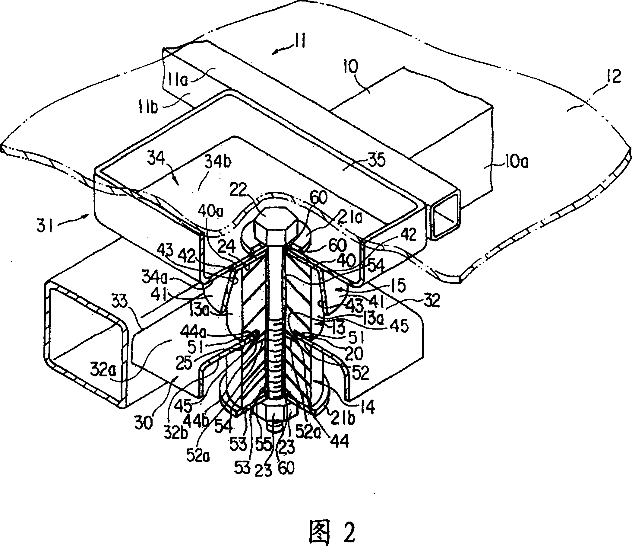
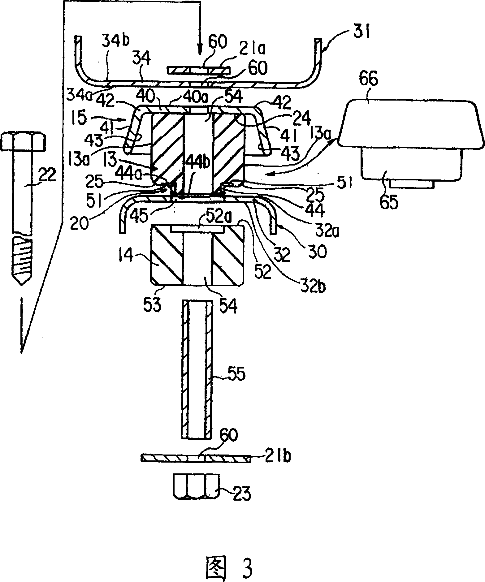
[0029] Hereinafter, a vehicle body mounting device according to a first embodiment of the present invention will be described with reference to FIGS. 1 to 3 .

[0030] The body 1 of an automobile is provided with a chassis frame 2 and a vehicle body 3 respectively. As shown in FIG. Further, front, rear, left, and right are defined on the basis of the traveling direction F of the automobile, and up and down are defined with respect to the chassis frame 2 by taking the direction in which the vehicle body 3 is located as the upward direction. In addition, FIG. 1 shows the left sides of the chassis frame 2 and the vehicle body 3 .

[0031] FIG. 2 shows a state in which a vehicle body 3 is fixed to a chassis frame 2 using a vehicle body mounting device 5 on the left side of the vehicle body 1 . The chassis frame 2 has side members 10 with a rectangular closed section extending in the front-rear direction. The vehicle body 3 has: a beam 11 extending in the left-right direction wit...

no. 2 approach

[0063] A second embodiment will be described with reference to FIG. 4 . The second embodiment does not use the body-side elastic body 13 described in the first embodiment, but uses a body-side elastic body 72 composed of a main body portion 70 and an extension portion 71 .

[0064] The main body portion 70 has, for example, a cylindrical shape, and its upper surface 73 is integrally fixed to the base portion 40 of the protective member 15 . The extension portion 71 extends from the outer peripheral edge 74 of the upper surface 73 of the main body portion 70 along the inner surface 43 of the receiving portion 41 away from the outer surface 75 of the main body portion 70 to cover the front edge 80 of the receiving portion 41 .

[0065] The body side elastic body 72 is formed integrally by vulcanization molding using rubber, for example, as in the first embodiment. In addition, the body side elastic body 72 is installed between the chassis bracket 30 and the body bracket 31 like...


PUM


Abstract

Provided is a body mount device capable of making the number of parts less while retaining sufficient load characteristics. The body mount device 5 has a body side elastic body 13 between a chassis side bracket 30 and a body side bracket 31 and has a protection member 15 between the body side bracket 31 and the body side elastic body 13. The protection member 15 is positioned between the body side bracket 31 and the body side elastic body 13 and is provided with a base part 40 for protecting an upper surface 24 of the body side elastic body 13; and a receiving part 41 extending from an outer peripheral edge 42 of the base part 40 toward the chassis side while leaving from an outer surface 13a of the body side elastic body 13 and receiving deformation of the body side elastic body 13. A guide member 20 for positioning the body side elastic body 13 relative to the chassis side bracket 30 is provided between the body side elastic body 13 and the chassis side bracket 30.

Description

technical field [0001] The present invention relates to a body mount device for absorbing a load acting between a chassis frame and a vehicle body and fixing the chassis frame and the vehicle body. Background technique [0002] The chassis frame and the vehicle body of the vehicle body of the conventional vehicle are formed separately, for example, the vehicle body is fixed on the chassis frame by using a vehicle body mounting device. [0003] In such automobiles, for example, depending on the state of the road surface, a load that pushes each other or separates the chassis frame and the vehicle body sometimes occurs. Therefore, the vehicle body mounting device is required not only to simply fix the chassis frame and the vehicle body, but also to absorb the above-mentioned load. [0004] In response to the above requirements, in order for the vehicle body mounting device to absorb loads such as pressing the chassis frame and the vehicle body, the body side elastic body is i...

Claims


Application Information

Patent Timeline
Patent Type & Authority Patents(China)
IPC IPC(8): B62D24/02B62D27/04F16F15/08
Inventor 中尾宪一郎山田直章中川速水
Owner MITSUBISHI MOTORS CORP
Learn More