Double sealing apparatus for valve closure member

A technology of opening and closing parts and double seals, which is applied in the direction of valve devices, lift valves, engine components, etc., and can solve problems such as poor deformation compensation performance, imprecise seals, and blockages

Inactive Publication Date: 2007-05-30
DAZHONG VALVE FACTORY ZHEJIANG PROV
View PDF8 Cites 0 Cited by
  • Summary
  • Abstract
  • Description
  • Claims
  • Application Information

AI Technical Summary

Problems solved by technology

[0002] The current valve seals generally adopt soft seals made of soft materials such as rubber, and hard seals made of hard materials such as stainless steel and copper. The soft seal has the advantages of good deformation compensation and tight sealing, but the soft seal material has low compressive strength and is easy to be crushed. , short life; the hard seal has the advantages of high compressive strength and long life, but the deformation compensation performance is poor, the processing precision is high, the seal is not tight, and it is difficult to repair after wear
There is also a combination of soft and hard seals, making full use of the advantages of soft seals with good deformation compensation, tight seals, and hard seals with high compressive strength and long life. This combination of soft and hard seals overcomes the shortcomings of both. However, this kind of soft and hard combined sealing device generally works first when the hard seal is closed. After closing and cutting off the fluid to cause a pressure difference before and after the seal, the pressure difference is used to drive the soft seal, so that the soft seal can function to form a secondary seal. , but this kind of drive soft seal device generally connects the soft seal with the high-pressure end through some small holes to form a drive channel. These holes are easily blocked by impurities in the liquid during the liquid flow and cannot drive the soft seal, making the soft seal invalid.

Method used


Image

  • Double sealing apparatus for valve closure member
  • Double sealing apparatus for valve closure member
  • Double sealing apparatus for valve closure member

Examples


Embodiment Construction

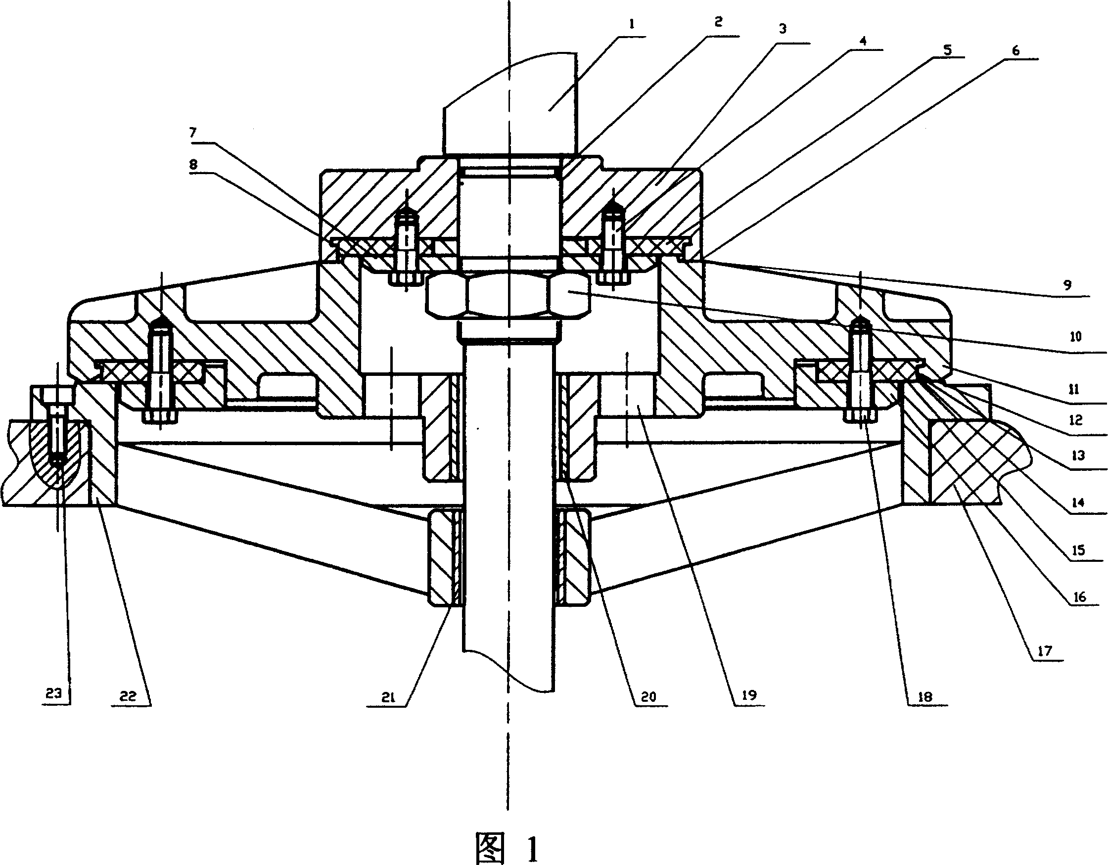
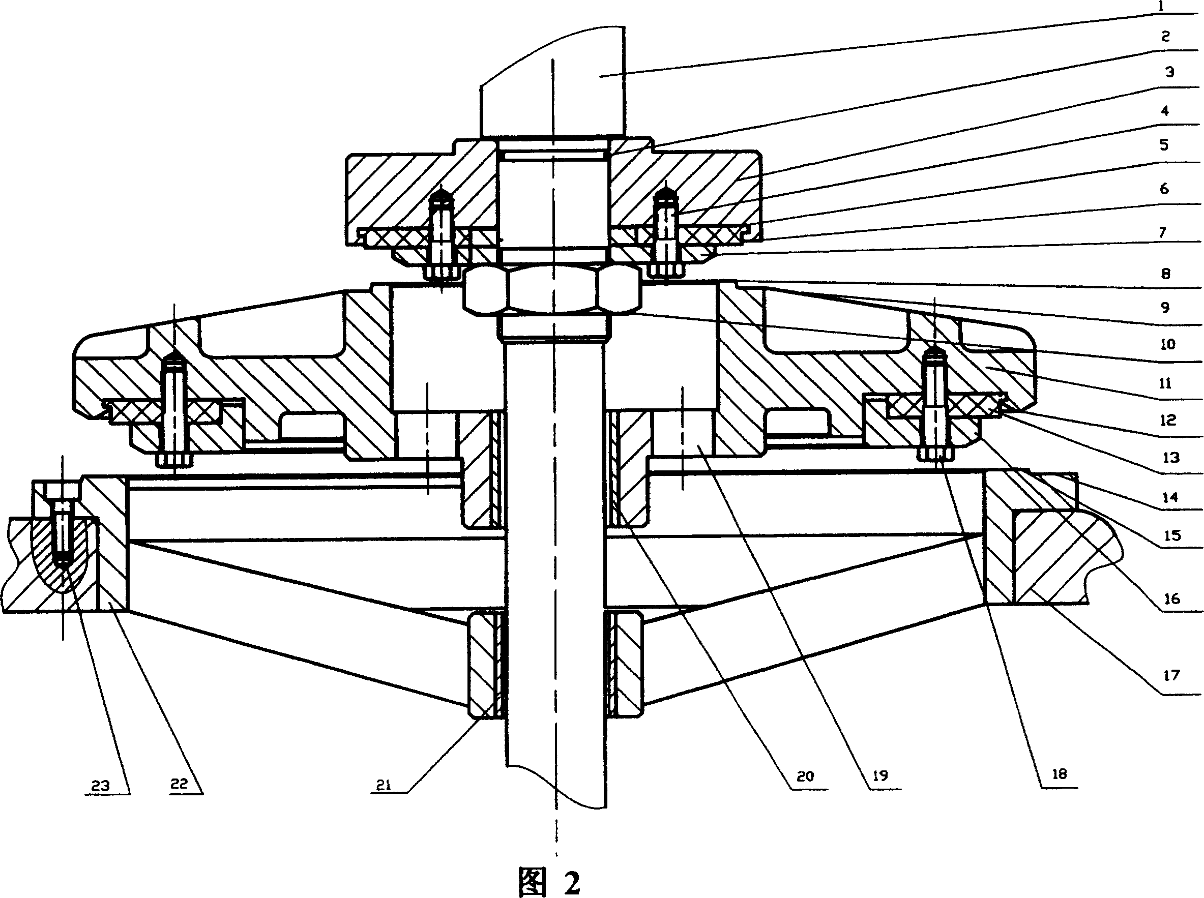
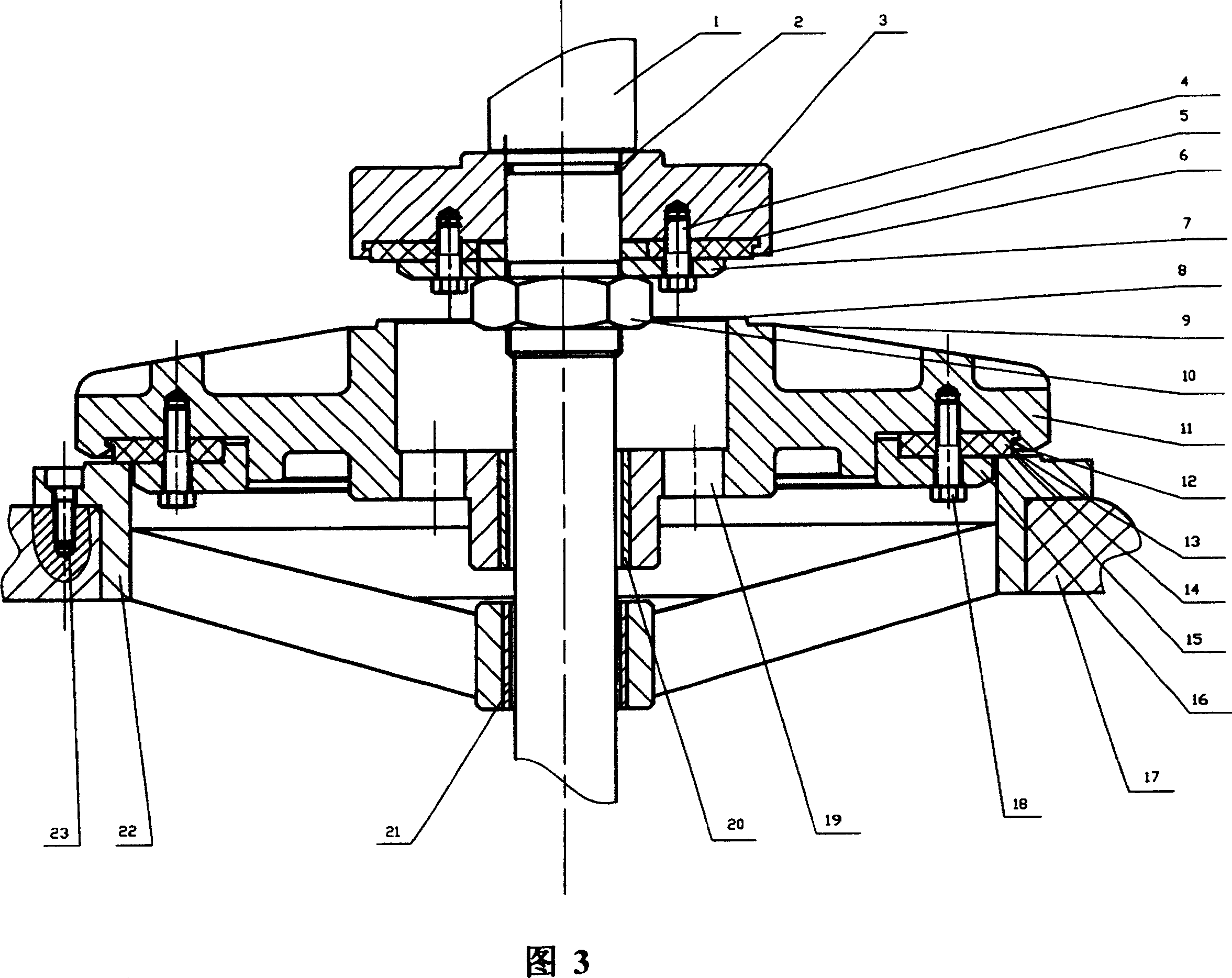
[0014] The present invention consists of a valve stem 1, a sealing ring 2, a slow closing valve plate 3, a slow closing soft seal 5, a slow closing hard seal 6, a slow closing soft sealing surface 8, a slow closing hard sealing surface 9, and slow closing valve plate fastening screws 4. Fast-closing fastening screw 18, valve seat fastening screw 23, small pressure plate 7, nut 10, fast-closing valve plate 11, fast-closing soft seal 13, fast-closing hard seal 12, large pressure plate 16, fast-closing soft sealing surface 15. Quick-closing hard sealing surface 14, valve seat 22, valve body 17, quick-closing valve plate cover 20, valve seat cover 21, and discharge hole 19 are composed.

[0015] The slow-closing valve plate 3 is installed on the valve stem 1 through the hole fit, the sealing ring 2 is installed at the joint between the slow-closing valve plate 3 and the valve stem 1 hole, and the slow-closing soft seal 5 is installed on the slow-closing valve plate 3, with a small ...


PUM


Abstract

The present invention is double sealing mechanism for stepped closing valve. The double sealing mechanism includes valve rod, slowly closing valve plate, slowly closing soft sealing, slowly closing hard sealing, small press plate, fast closing valve plate, fast closing soft sealing, fast closing hard sealing, large press plate, fast closing soft sealing plane, fast closing hard sealing plane, valve seat, valve body, etc. The slowly closing soft sealing and the small press plate are screwed on slowly closing valve plate, and all the slowly closing valve plate, the slowly closing soft sealing and the small press plate are screwed on the valve rod. The slowly closing hard sealing is welded on the slowly closing valve plate. The fast closing soft sealing is installed on the fast closing valve plate, and the large press plate to press the fast closing soft sealing is screwed to the fast closing valve plate. The valve seat is screwed to the valve body. The present invention has reliable sealing and long service life.

Description

Technical field: [0001] The invention belongs to a stage closing and sealing device for a valve, and relates to a double sealing device for a valve opening and closing part. Background technique: [0002] The current valve seals generally adopt soft seals made of soft materials such as rubber, and hard seals made of hard materials such as stainless steel and copper. The soft seal has the advantages of good deformation compensation and tight sealing, but the soft seal material has low compressive strength and is easy to be crushed. , short life; the hard seal has the advantages of high compressive strength and long life, but the deformation compensation performance is poor, the machining accuracy is high, the seal is not tight, and it is difficult to repair after wear. There is also a combination of soft and hard seals, making full use of the advantages of soft seals with good deformation compensation, tight seals, and hard seals with high compressive strength and long life. ...

Claims


Application Information

Patent Timeline
Patent Type & Authority Patents(China)
IPC IPC(8): F16K1/34
Inventor 李志鹏金志渊林加钱林永通
Owner DAZHONG VALVE FACTORY ZHEJIANG PROV
Why Eureka
Try Eureka