A fully automatic sintered brick stacking machine

A brick blanking machine and fully automatic technology, applied in the field of automatic sintering brick blanking machines, can solve the problems of reducing the quality and efficiency of the brick blanks, easily generating shaking, affecting the quality of the brick blanks, etc., to enhance the stability of movement and prevent extrusion. The effect of pressure damage and ensuring the quality of bricks

Active Publication Date: 2019-05-17
湖南省年年红新型建材有限公司
View PDF6 Cites 0 Cited by
  • Summary
  • Abstract
  • Description
  • Claims
  • Application Information

AI Technical Summary

Problems solved by technology

[0004] 1. The gripper of the coder is connected to the motor reducer through the lifting belt, so that the grabbed bricks can be lifted upwards, but because the clamping force of the gripper of the coder cannot be adjusted, especially when clamping bricks of different sizes , it is easy to cause the bricks to fall and be damaged by extrusion, which reduces the quality and efficiency of the bricks
[0005] 2. The gripper of the stacking machine is connected to the motor reducer through the lifting belt, so that the grabbed bricks can be lifted upwards. However, due to the flexibility of the lifting belt itself and the high humidity of the bricks, the gripper of the stacking machine bears a large weight , it is easy to shake during the lifting process, resulting in damage to the bricks, which seriously affects the quality and efficiency of the subsequent code blanks
[0006] 3. When the walking trolley stops, the impact force is relatively large, so that the adobes held by the gripper of the adobe coder are prone to fall, which affects the quality of the adobes

Method used


Image

  • A fully automatic sintered brick stacking machine
  • A fully automatic sintered brick stacking machine
  • A fully automatic sintered brick stacking machine

Examples


Embodiment 1

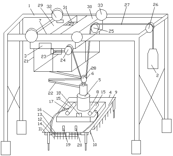
[0045] see figure 1 , a fully automatic sintered brick stacking machine, including a frame 1, a counterweight 2, a main machine 3, a blank clamping device 4 electrically connected to the main machine 3, a rotating device 5, a lifting device 6 and a traveling device 7, and the traveling device 7 Slidingly connected on the beam of the frame 1, the clamping device 4 includes a chuck 8, a telescopic frame 9 connected to the chuck 8 and a multi-row clamp 10 connected to the inner wall of the telescopic frame 9, the chuck 8 and the rotating device 5 fixed connection, the clamp 10 is composed of a cylinder 11, a connecting rod 12, a telescopic rod 13 and a splint 14, the cylinder 11 is fixed on the telescopic frame 9, the telescopic rod 13 is connected with the piston rod of the cylinder 11, and the splint 14 is worn on the telescopic rod 13 , the adjacent splints 14 are connected by connecting rods 12 to form a linkage, the chuck 8 is connected with an air storage tank 15, the cylin...

Embodiment 2

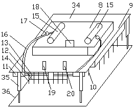
[0050] see figure 1 and figure 2 , a fully automatic sintered brick stacking machine, including a frame 1, a counterweight 2, a main machine 3, a blank clamping device 4 electrically connected to the main machine 3, a rotating device 5, a lifting device 6 and a traveling device 7, and the traveling device 7 Slidingly connected on the beam of the frame 1, the clamping device 4 includes a chuck 8, a telescopic frame 9 connected to the chuck 8 and a multi-row clamp 10 connected to the inner wall of the telescopic frame 9, the chuck 8 and the rotating device 5 fixed connection, the clamp 10 is composed of a cylinder 11, a connecting rod 12, a telescopic rod 13 and a splint 14, the cylinder 11 is fixed on the telescopic frame 9, the telescopic rod 13 is connected with the piston rod of the cylinder 11, and the splint 14 is worn on the telescopic rod 13 , the adjacent splints 14 are connected by connecting rods 12 to form a linkage, the chuck 8 is connected with an air storage tan...

Embodiment 3

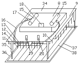
[0056] see figure 1 and image 3, a fully automatic sintered brick stacking machine, including a frame 1, a counterweight 2, a main machine 3, a blank clamping device 4 electrically connected to the main machine 3, a rotating device 5, a lifting device 6 and a traveling device 7, and the traveling device 7 Slidingly connected on the beam of the frame 1, the clamping device 4 includes a chuck 8, a telescopic frame 9 connected to the chuck 8 and a multi-row clamp 10 connected to the inner wall of the telescopic frame 9, the chuck 8 and the rotating device 5 fixed connection, the clamp 10 is composed of a cylinder 11, a connecting rod 12, a telescopic rod 13 and a splint 14, the cylinder 11 is fixed on the telescopic frame 9, the telescopic rod 13 is connected with the piston rod of the cylinder 11, and the splint 14 is worn on the telescopic rod 13 , the adjacent splints 14 are connected by connecting rods 12 to form a linkage, the chuck 8 is connected with an air storage tank ...


PUM


Abstract

The invention discloses a full-automatic sintered brick setting machine. The full-automatic sintered brick setting machine is characterized in that a chuck plate and a rotating device are fixedly connected; cylinders are fixed to a telescopic rack; telescopic rods are connected with piston rods of the cylinders; clamping plates penetrate through the telescopic rods; the cylinders communicate with gas storage tanks through gas distributing tubes; the gas inlet ends of the gas distributing tubes are connected with gas pressure regulators; an opposite type photoelectric sensor, an inductive sensor and a magnetic sensor are electrically connected with a main engine; a lifting part is composed of a servo motor, a driving chain wheel, a first fixed pulley, a second fixed pulley, a chain and a driven chain wheel; the servo motor, the driving chain wheel and the first fixed pulley are all arranged on a traveling device; the second fixed pulley is arranged at the end of a cross beam of a machine frame; the driven chain wheel is arranged on the rotating device; and the driving wheel is driven through a stepping motor arranged on a first rack plate. According to the full-automatic sintered brick setting machine, integrated operation of clamping, conveying and stacking of green bricks is achieved through the main engine; and the stacking quality and efficiency of the green bricks are greatly improved.

Description

technical field [0001] The invention relates to the technical field of sintered brick mechanical equipment, in particular to a fully automatic sintered brick stacking machine for fast and orderly stacking. Background technique [0002] Under the current situation of rising labor costs and vigorous development of science and technology, the method of replacing human work with automation equipment is increasingly favored by modern brick-making enterprises. On the adobe production line, the use of the automatic adobe stacking machine makes the adobe stacking simple and fast, greatly reducing labor costs. The automatic stacking machine is a mechanical device that automatically divides, grabs, moves and stacks bricks in sequence. The automatic stacking machine is mainly composed of a splitting device, a blank clamping device, a walking device, a lifting device, a rotating device, and a hydraulic system. It is composed of an electrical system, etc., wherein the lifting device is ...

Claims


Application Information

Patent Timeline
Patent Type & Authority Patents(China)
IPC IPC(8): B65G61/00
CPCB65G61/00
Inventor 何娟石一利
Owner 湖南省年年红新型建材有限公司
Why Eureka
Try Eureka