'Menneimasi pendulum arm' and stalking mechanical leg

A technology of mechanical legs and horses, which is applied in the direction of mechanical equipment, transmission devices, belts/chains/gears, etc., and can solve problems such as difficult to popularize, expensive, and large inertial impact force

Inactive Publication Date: 2007-03-21
熊介良
View PDF5 Cites 0 Cited by
  • Summary
  • Abstract
  • Description
  • Claims
  • Application Information

AI Technical Summary

Problems solved by technology

In this way, the inertial impact force generated when the stride turns back is large, and the driving force required is large. It is not suitable for f

Method used


Image

  • 'Menneimasi pendulum arm' and stalking mechanical leg
  • 'Menneimasi pendulum arm' and stalking mechanical leg
  • 'Menneimasi pendulum arm' and stalking mechanical leg

Examples


Embodiment 2

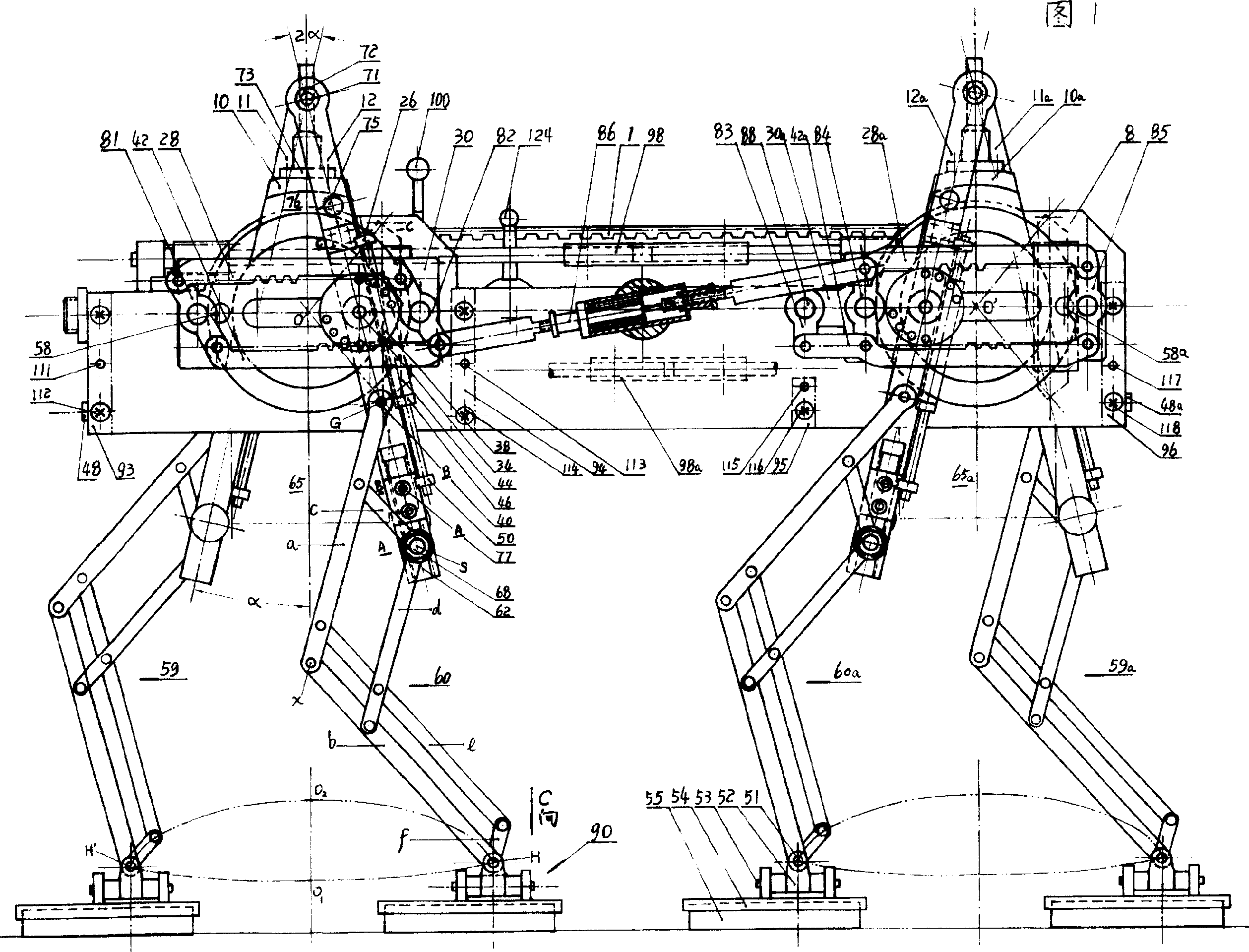
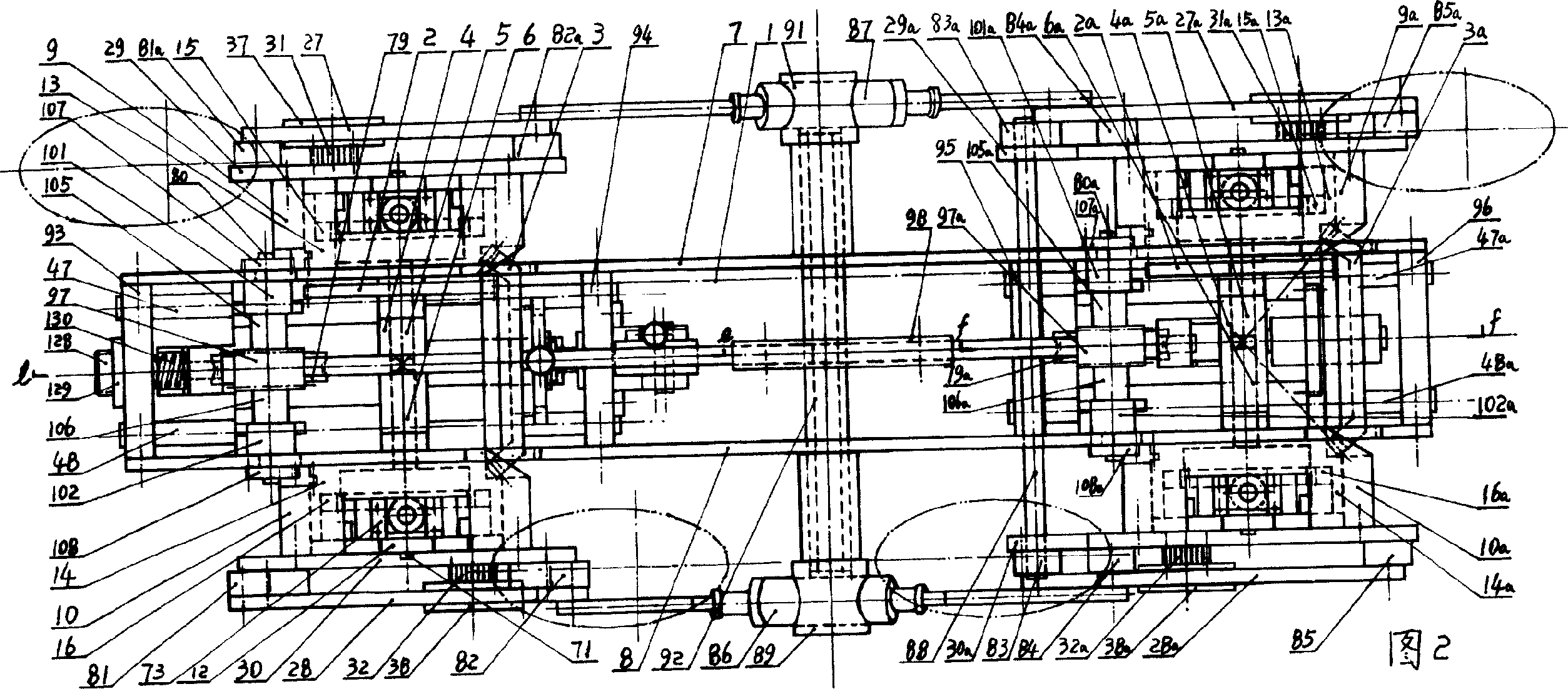
[0084] Embodiment 2, Figures 18, 19, 20, and 21 are examples of walking mechanical legs imitating insects or crawling gaits in the drive rod and walking mechanical leg device of the present invention, except that there are a few differences in the scaling leg lifting mechanism for walking Outside, the structural design of embodiment 1 can be copied indiscriminately for other main parts, if each leg of this embodiment all walks by fixed 2α pendulum angle, so just can save large, medium and small stepped stride gear or stepless Change the stride gear, just can save the worm wheel (79) on the relevant front and rear frame in the mechanism, (79a), worm screw (97), (97a) and four pinions (107), (108); 107a), (108a) etc. a large number of parts, the bevel gear (3) in the steering mechanism like this, (3a) just can be with ring gear sleeve (13), (14); On (13a), (14a) The bevel gear wheel point of the bevel gear has been kept in constant mesh, and the corresponding mechanism of the ca...


PUM


Abstract

A walking mechanical leg based on Menneimasi pendulum arm is disclosed. The Menneimasi pendulum arm doing reciprocating swining along ellipse trace is hinged to the fixed point of pantograph. The reducing point sliding in the slot on said arm and the dual-parallelogram reversing mechanism are combined to realize telescopic control, pace regualtino, clutch and self-locking. The condyle joint of pantograph is linked to leg mechanism.

Description

1. Technical field: [0001] The invention relates to a series of walking or crawling devices for various purposes such as robots, robotic animal parks, four-legged walking vehicles, artificial feet, insect or animal walking toys, and large, medium, small, and miniature products. 2. Background technology: [0002] In nature, human beings, birds, animals, insects, etc. all walk by swinging and stretching movements of their legs. Learning from nature, imitating biological legs and feet to design new mechanical legs is a shortcut method. The walking mechanism of the walking robot disclosed or reported by various media at present adopts hydraulic oil cylinder, ball screw etc. as linear drive mostly, or directly all uses a driver on each joint point of leg structure. In this way, the inertial impact force produced when the stride turns back is large, and the driving force required is large, so it is not suitable for fast walking. Using many drivers will inevitably have the disadvan...

Claims


Application Information

Patent Timeline
IPC IPC(8): F16H27/00
Inventor 熊介良
Owner 熊介良
Why Eureka
Try Eureka