Lateral current collector

A technology of lateral flow and flow-receiving sliding shoes, which is applied in the field of current collectors, can solve problems such as unfavorable flow, achieve fast dynamic response, facilitate maintenance and installation, and achieve the effect of retraction and locking

Inactive Publication Date: 2007-06-13
NAT UNIV OF DEFENSE TECH
View PDF9 Cites 0 Cited by
  • Summary
  • Abstract
  • Description
  • Claims
  • Application Information

AI Technical Summary

Problems solved by technology

However, the single pendulum mechanism has obvious disadvantages. In the current receiver of the single pendulum mechanism, the current receiver slide shoe swings relative to the current receiver base, and the current receiver slide shoe and the current receiver rail surface present an included angle, and the included angle varies with the swing. In fact, the appearance of the included angle makes the line contact between the flow-receiving shoe and the flow-receiving rail, which is unfavorable for flow-receiving

Method used


Image

  • Lateral current collector
  • Lateral current collector
  • Lateral current collector

Examples


Embodiment Construction

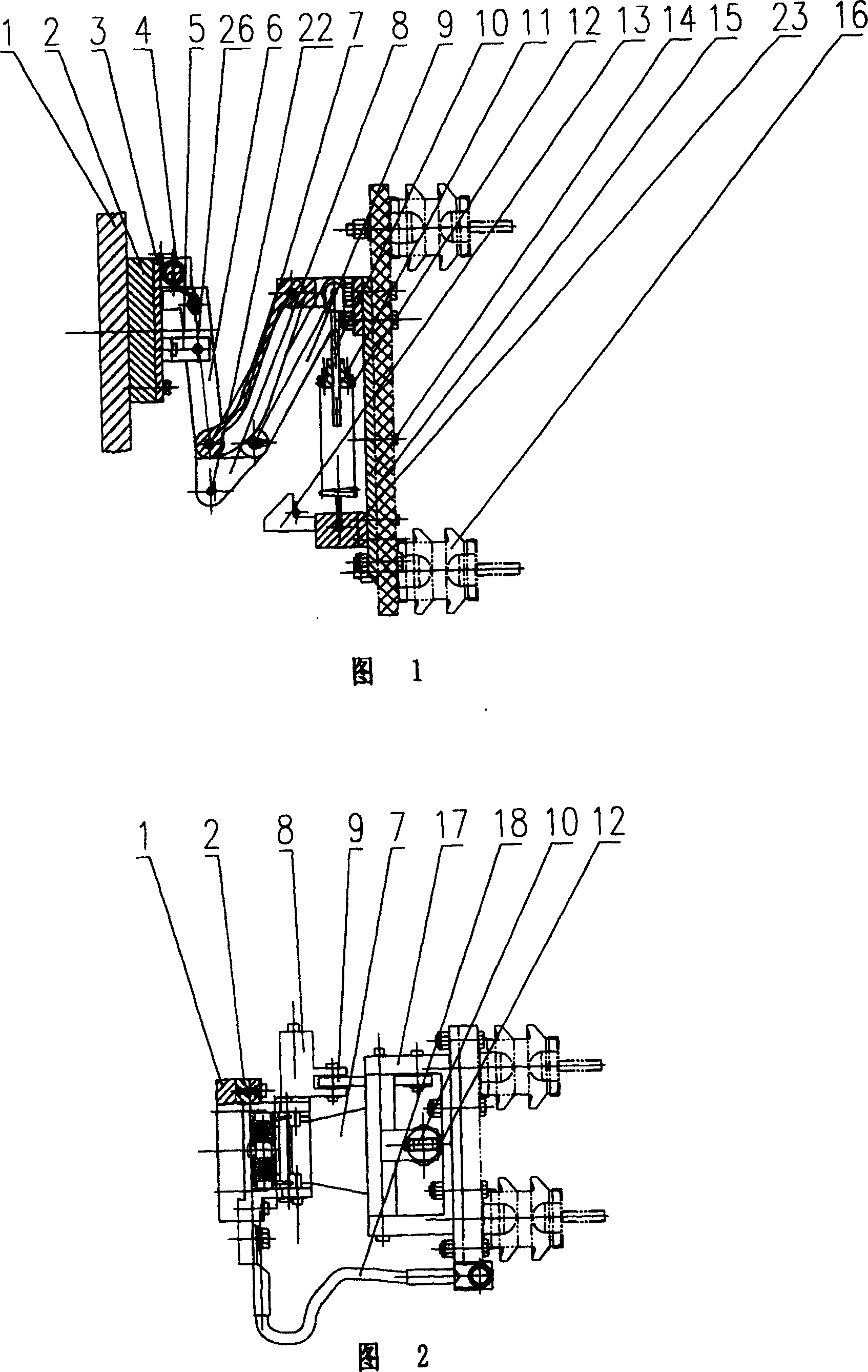
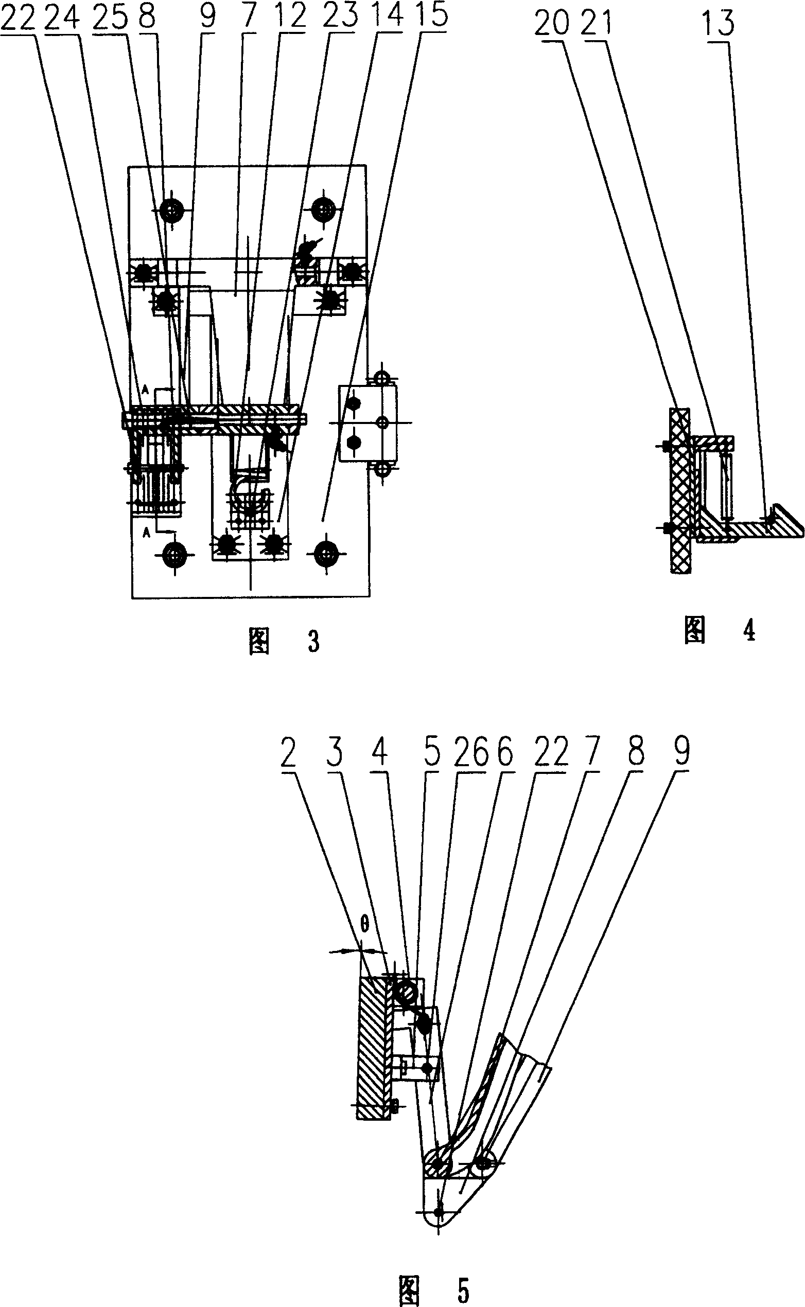
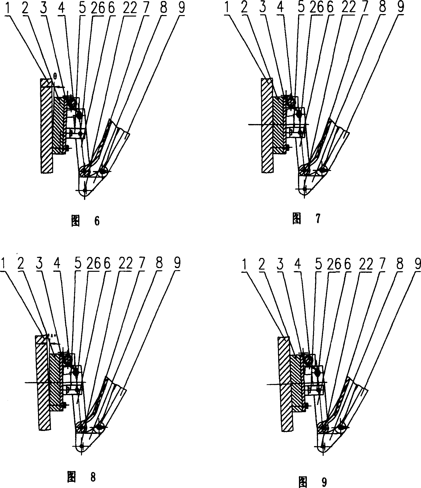
[0032] The present invention will be further described in detail below in conjunction with the accompanying drawings.

[0033]As shown in Figure 1, Figure 2 and Figure 3, the lateral flow receiver of the present invention includes a flow receiving shoe 2, a swing mechanism, and a bottom plate 14. One end of the swing mechanism is fixed on the bottom plate 14, and the other end is connected to the flow receiving shoe. 2 is connected, the other side of the bottom plate 14 is connected to the insulating bottom plate 15, the insulating bottom plate 15 is connected to the power supply device through the insulator 16, and the power supply device is connected to the current receiving shoe 2 through the drain cord 18. The swing mechanism includes a four-link mechanism, a final pendulum rod 6 and a tension spring 12. The four-link mechanism is connected to each other by the main pendulum rod 7, the auxiliary pendulum rod 9, the fork-shaped pendulum rod 8 and the main pendulum rod support 1...


PUM


Abstract

A lateral current collector is composed of a current collecting slide block, a swing mechanism, and a base plate. Said swing mechanism connected between said slide block and base plate consists of a 4-connecting-rod unit comprising primary swinging bar, secondary swinging bar, swinging fork bar and the supporter of primary swinging bar, a final swinging bar, and a tensional spring connected between primary swinging bar and base plate.

Description

Technical field [0001] The invention mainly relates to the field of current collectors, and particularly refers to a lateral current collector suitable for a normally conductive maglev train. Background technique [0002] In the prior art, the power supply of the normal-conducting medium and low-speed maglev trains and the power supply of the high-speed maglev trains in the low-speed section are the same as subways and light rails. They all use the three-track or four-track power supply method, and then pass through the current collector. The dynamic contact between the current receiving shoe and the power supply rail leads the electric energy to the maglev train. In the three-track power supply, there are three current collection methods: upper current collection (the friction current receiving surface of the current receiving rail faces upward), the lower current receiving (the friction current receiving surface of the current receiving rail faces downward) and the side current...

Claims


Application Information

Patent Timeline
Patent Type & Authority Patents(China)
IPC IPC(8): B60L5/00
Inventor 陈革常文森龙志强李杰李宁
Owner NAT UNIV OF DEFENSE TECH
Why Eureka
Try Eureka