Collapsible container

A technology of container and top ring, applied in the direction of variable capacity container, container, shallow container, etc., can solve problems such as weakening wall parts

Inactive Publication Date: 2007-07-11
DART IND INC
View PDF2 Cites 1 Cited by
  • Summary
  • Abstract
  • Description
  • Claims
  • Application Information

AI Technical Summary

Problems solved by technology

This need for the actual bending of the members in addition to the folding at the film hinges is so pronounced that, at least in some examples shown in

Method used


Image

  • Collapsible container
  • Collapsible container
  • Collapsible container

Examples


Embodiment Construction

[0025] In the drawings, the features of the embodiments shown in FIGS. 1-11 are marked with two-digit numbers. Features in the embodiment shown in Figures 12-22 are designated by the same reference numerals prefixed with a 1 .

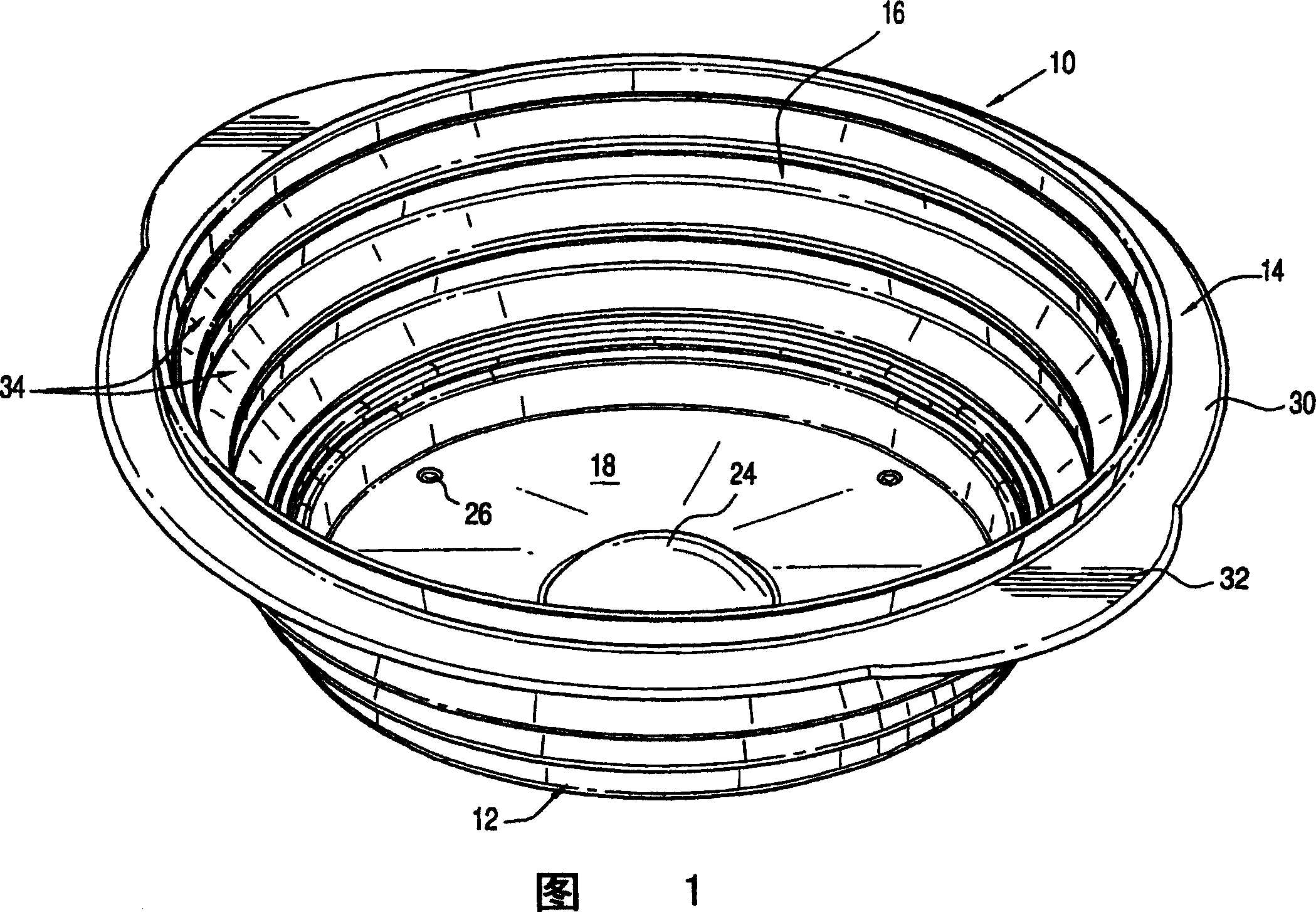
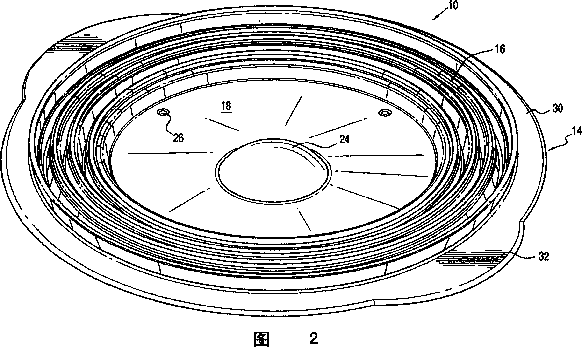
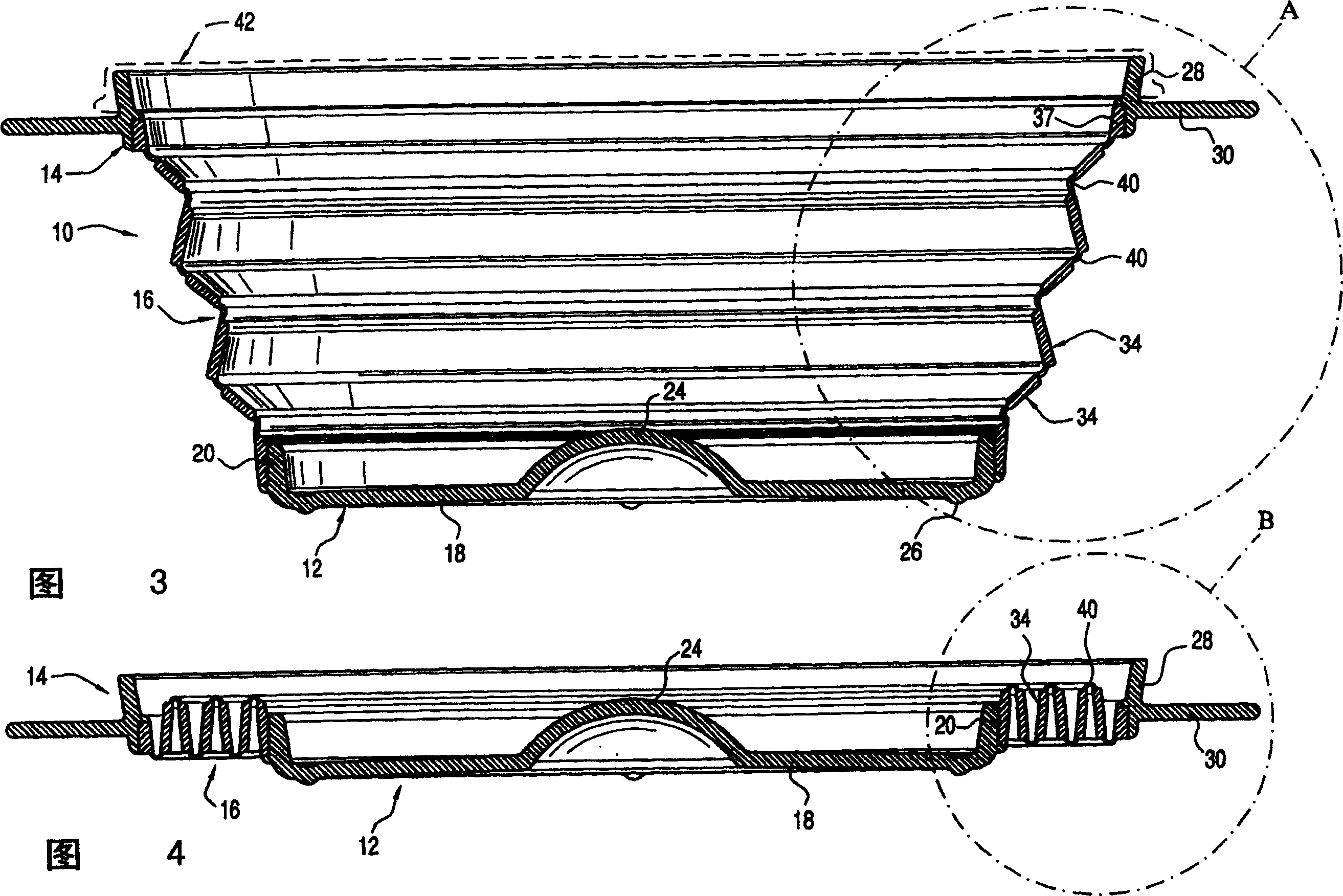
[0026] Referring now more particularly to the drawings, a collapsible container 10 includes a base 12, a top ring 14, and a folded wall 16 extending therebetween. Base 12 is a substantially rigid member that includes a base 18 including a peripheral upstanding base wall 20 . The base may be flat, and preferably includes a centrally located, slightly upwardly extending depressing area or bump 24 of any suitable shape (such as a dome) to assist in unfolding the container, as will be described subsequently. . The base also preferably has a set of small feet depending from the bottom 18 of the base which form a knob 26 or a continuous foot rib (not shown).

[0027] The top ring 14 includes a continuous or annular ring wall 28 with a peripheral horizonta...


PUM


Abstract

A collapsible container with angularly related multiple folding sections, each section extending at an angle to the vertical, and flexure zones between adjacent sections for flexibly moving the sections between a first open position in the expanded container and a second position folded upon itself in the collapsed container, the flexure zones resisting movement of the sections in both the fully expanded container and the collapsed container, as well as any intermediate position wherein only selected flexure zones are in an open position.

Description

technical field [0001] The present invention generally relates to molded plastic containers of the type commonly used for various purposes including storage of food or non-edible items, such containers preferably being adapted to receive suitable seals or lids. More specifically, the present invention relates to a type of container that is not rigid like conventional bowls, but collapses or folds into a compact state when empty for easy storage . Background technique [0002] Containers of this type, cups, bowls and the like are generally known in the art and come in a variety of forms. These containers include collapsible cups or glasses in which the glass is formed from telescopically stacked annular wall members that can slide relative to each other between a fully extended condition and a collapsed condition. When the wall members are not integrally formed and slide freely relative to each other, leaks are likely to occur and serve no practical purpose other than as te...

Claims


Application Information

Patent Timeline
IPC IPC(8): B65D21/08A45F3/20B65D1/32B65D1/34B65D1/40B65D1/44B65D6/16B65D8/14
CPCB65D21/086B65D1/32B65D1/44B65D7/24
Inventor D·库苏马P·M·卡德H·J·B·鲁构
Owner DART IND INC
Why Eureka
Try Eureka