Umbrella valves dedicated to piezoelectric pumps

A technology for umbrella valves and piezoelectric pumps, which is applied to parts, control valves, and valve devices of pumping devices for elastic fluids, and can solve the problems of poor consistency and air tightness of pump valves, poor product matching capabilities, and Air leakage and other problems can be improved to achieve the effect of improving the sealing effect and working performance, obvious cost-effective comprehensive features, and convenient installation and use.

Inactive Publication Date: 2011-12-21
胡军 +1
View PDF12 Cites 11 Cited by
  • Summary
  • Abstract
  • Description
  • Claims
  • Application Information

AI Technical Summary

Problems solved by technology

[0023] However, although the above-mentioned background technology has many advantages, there are also shortcomings and deficiencies in various degrees: the above-mentioned various valve bodies have complex structures, many processing steps, exquisite craftsmanship, high manufacturing costs, and expensive prices. The matching of electric pump products has strict conditions and requirements for conveying (medium) liquid, and the assembly process is complicated, the overall cost is high, the matching ability of the product is poor, and the market is difficult to promote and popularize
[0026] 1. Metal and single cantilever beam valves made of different shapes and structures are difficult to use process tooling to ensure the flatness of the installed valve body and the suitability of the strength of the fixed pump valve, resulting in poor consistency and air tightn...

Method used


Image

  • Umbrella valves dedicated to piezoelectric pumps
  • Umbrella valves dedicated to piezoelectric pumps
  • Umbrella valves dedicated to piezoelectric pumps

Examples


Embodiment 1

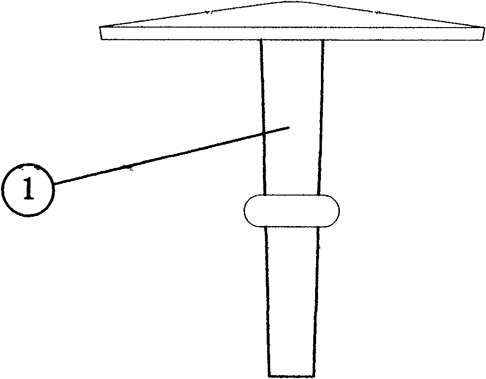
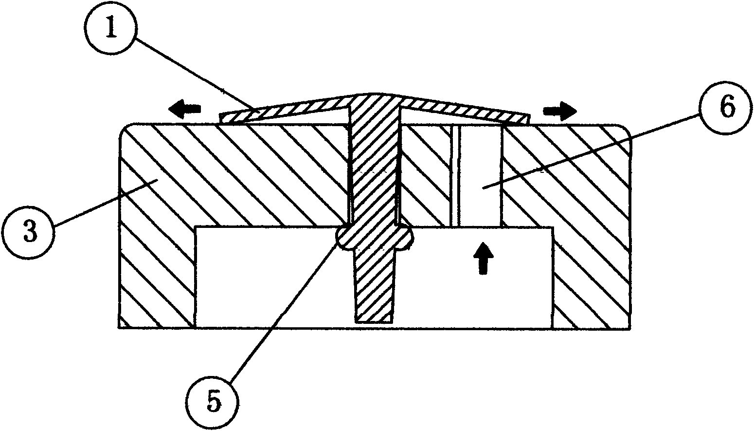
[0053] Embodiment 1: Referring to Fig. 2(a), this is a structure in which the umbrella valve A 1 is connected and matched with the valve frame A 3, and the umbrella handle in the umbrella valve A 1 passes (or passes through) and is located in the valve frame A 3 The hole in the center, the limit boss 5 on the umbrella handle is stuck outside the through hole of the valve frame A3, because the pressure of the fluid on the upper and lower sides of the umbrella surface of the umbrella valve A1 is different, the umbrella valve A1 is opened The umbrella-shaped plane of the umbrella-shaped plane can reciprocate up and down, just like the wings of a flying butterfly move up and down. The umbrella-shaped lower plane opened by the umbrella-shaped valve A 1 and the fluid inlet and outlet on the valve frame A 3 are opened and closed through the flow hole 6 With the cooperation, the passage hole 6 has the characteristics of opening and closing as a whole. In addition, there is another way...

Embodiment 2

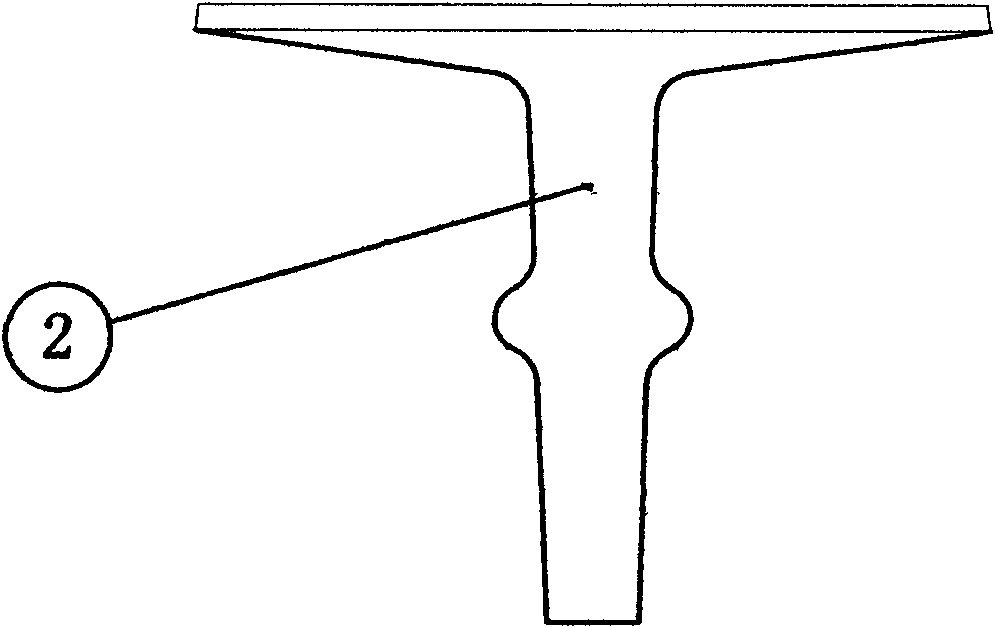
[0054]Embodiment 2: Referring to Fig. 2(b), it is basically the same as Fig. 2(a), the difference is that the umbrella valve in Fig. 2(b) is umbrella valve B 2, which is an umbrella valve B 2 with valve The cross-sectional diagram of the connection and cooperation of the frame B 4, the umbrella handle of the upper and lower umbrella valve B 2 passes through and is located in the center hole of the valve frame B 4, and the limit boss 5 on the umbrella handle is stuck on the valve frame B 4 Outside the through hole, due to the different pressures of the fluid acting on the upper and lower sides of the umbrella surface of the umbrella valve, the umbrella-shaped lower inclined surface of the umbrella valve B 2 and the fluid inlet and outlet on the valve frame B 4 are opened and closed through the flow hole 6. Closed cooperation, in order to cooperate better, the umbrella-shaped lower slope opened by the umbrella valve B 2 corresponds to the slope above the valve frame B 4 and serve...

Embodiment 3

[0055] Embodiment 3: It is the combination of the above two embodiments, that is, the valve handle of the umbrella valve has a limited boss 5, the upper surface of the opened umbrella is raised or flat, and the lower surface of the opened umbrella is It is an upward circular inclined surface or a circular arc surface, as a matching surface with the fluid inlet and outlet of the valve frame through the flow hole (6).

[0056] see image 3 and Figure 4 , the valve frame A 3 is used as the first structure schematic diagram, the central through hole is used to pass through the handle of the umbrella valve, and the central through hole is surrounded by three flow holes 6 with arc-shaped grooves in cross-section, which are used as fluid passage through.

[0057] see Figure 5 and Figure 6 , the valve frame A 3 is used as the second structural diagram, which is basically the same as image 3 and Figure 4 , the difference is that four passage holes 6 with arc-shaped grooves in ...


PUM

PropertyMeasurementUnit
Thicknessaaaaaaaaaa
Thicknessaaaaaaaaaa
Shore hardnessaaaaaaaaaa

Abstract

An umbrella valve dedicated for use in a piezoelectric pump. Among micropump pump valves are actuation source-less valve, piezoelectrically actuated valve, thermally actuated valve, memory alloy valve, and piezoelectric valve, all of which have a certain shortcoming, for instance, the valves have complex structures and increased manufacturing costs, some provide a product with poor consistency and poor air-tightness. The umbrella valve dedicated for use in the piezoelectric pump structurally consists of the umbrella valve (A1) and a valve frame (A3). A valve rod of the umbrella valve is passed through and arranged at a central through hole of the valve frame. Distributed around the central through hole of the valve frame is a flow-pass through hole (6). The flow-pass through hole correspondingly matches the opening and closing of the umbrella valve that is opened. The umbrella valve is provided with characteristics of a simple structure, increased sensitivity, great sealing effect, reduced manufacturing costs, and great operational performance, and is applicable in the fields and scenarios of various fluids, comprising gases, water, and specifically liquids, such as in water processing, chemical engineering analysis, medical equipment, biomedicine, and automatic control.

Description

1. Technical field [0001] The invention relates to a micropump valve, in particular to an umbrella valve specially used for piezoelectric pumps. 2. Background technology [0002] The micropump valves in the background technology include non-excitation source valves (passive valves), piezoelectric actuation valves, thermal actuation valves, electrostatic actuation valves, magnetic actuation valves, electromagnetic / electrostatic actuation valves, memory alloy valves, and piezoelectric valves. Wait. [0003] The characteristics of the above valves are: [0004] 1. Non-excitation source valve: It can be divided into two types: cantilever beam check valve and double door valve. The working principle of this valve is that when the cantilever beam is opened by positive pressure, liquid or gas enters the pump chamber, the cantilever beam is closed by reverse pressure, and the liquid or gas is directional squeezed under the action of the one-way valve. discharge. [0005] The pro...

Claims


Application Information

Patent Timeline
IPC IPC(8): F04B53/10
CPCF04B53/1037F04B53/1065F16K15/148
Inventor 胡军杨竹君
Owner 胡军
Why Eureka
Try Eureka