Piezoelectric/electrostrictive structure and method for manufacturing the same

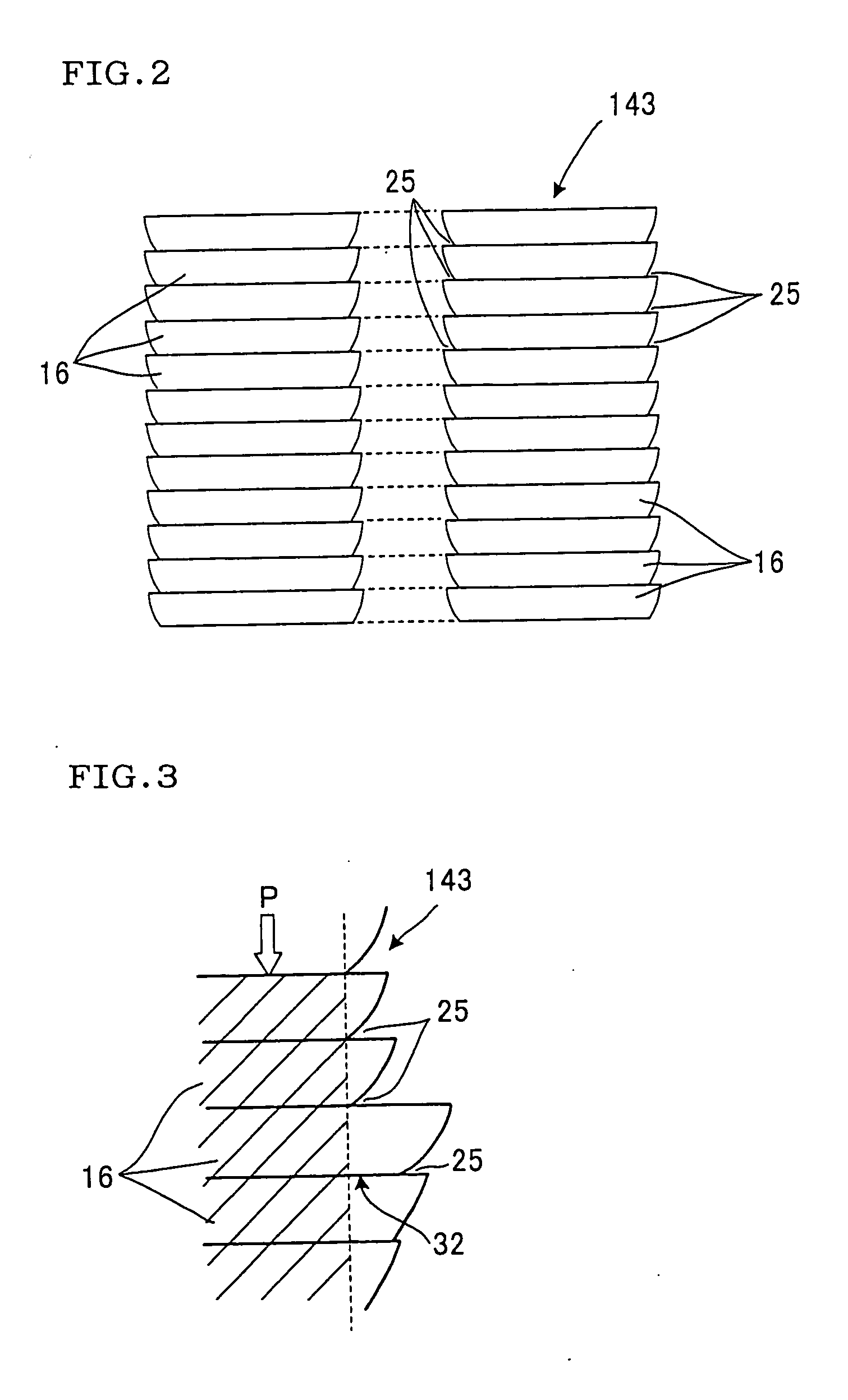
a technology of electroelectric structure and electromechanical structure, which is applied in the direction of electromechanical/electrostrictive device details, device details, generators/motors, etc., can solve the problems of easy damage to actuators, serious decline in the reliability of printing apparatuses, and damage to the interface between green sheets b>16/b>, etc., to achieve a large force, minimize a force, and high durability

Inactive Publication Date: 2005-12-01
NGK INSULATORS LTD
View PDF12 Cites 10 Cited by
  • Summary
  • Abstract
  • Description
  • Claims
  • Application Information

AI Technical Summary

Benefits of technology

[0046] On the other hand, when the direction in which the tensile stresses are applied to the piezoelectric / electrostrictive bodies is microscopically observed, the observation shows that the tensile stresses are not applied perpendicularly to the interfaces between the piezoelectric / electrostrictive bodies but are applied obliquely to the piezoelectric / electrostrictive bodies because the side faces of the piezoelectric / electrostrictive structure have the notches. Therefore, the piezoelectric / electrostrictive structure has high durability. When the piezoelectric / electrostrictive structure is used as an actuator, distortable parts (piezoelectric / electrostrictive actuating parts) of the piezoelectric / electrostrictive structure can be readily distorted because the thin films have a small thickness and the force of the thin films against the displacement is quite small, that is, the thin films can minimize a force for preventing the displacement. Therefore, the piezoelectric / electrostrictive structure is suitable for inkjet heads that need to have a large force for discharging ink.
[0047] Since the first and second piezoelectric / electrostrictive structures have the above advantages, the reliability of the structures is not deteriorated if the aspect ratio thereof is increased. Since an increase in aspect ratio leads to a decrease in buckling strength, a large pressure cannot be used when the structures are prepared. However, the structures obtained have high strength and are hardly damaged.
[0048] When the first or second piezoelectric / electrostrictive structure having a large aspect ratio is used to prepare partitions (piezoelectric / electrostrictive actuating parts) forming actuators included in an inkjet head, the inkjet head has high reliability and can provide high-resolution images. This is because when the partitions have a large aspect ratio, the partitions and ink chambers (cells) can be densely arranged in the inkjet head without reducing the volume of the ink chambers and without causing an increase in component-mounting area.
[0049] The first or second piezoelectric / electrostrictive structure having a large aspect ratio can be greatly distorted with a constant voltage. When the piezoelectric / electrostrictive structure is used to prepare piezoelectric / electrostrictive actuating parts of actuators included in a liquid-discharging unit placed in a DNA microarrayer, the volume of cells (liquid chambers) can be greatly varied and a large amount of liquid can be discharged. In other words, this means that a desired amount of displacement (a desired amount of discharged liquid) can be achieved with low voltage. That is, an energy-efficient liquid-discharging unit can be prepared using the piezoelectric / electrostrictive structure. Since the piezoelectric / electrostrictive structure has a large aspect ratio, the structure is advantageous in achieving a good balance between displacement and generated force. Since a great change in volume can be achieved with a small force, high-viscosity liquid can be constantly discharged.

Problems solved by technology

The actuator 131 prepared by the green sheet-stacking process has a problem in that the interfaces between the green sheets 16 are damaged in some cases when the ceramic green compact 143 is fired.
Therefore, such actuators are readily damaged.
The damage of the actuator 131 leads to the leakage of ink from ink chambers 135 placed in the inkjet head 130 and therefore leads to a serious decline in the reliability of printing apparatuses.

Method used


Image

  • Piezoelectric/electrostrictive structure and method for manufacturing the same
  • Piezoelectric/electrostrictive structure and method for manufacturing the same
  • Piezoelectric/electrostrictive structure and method for manufacturing the same

Examples


Embodiment Construction

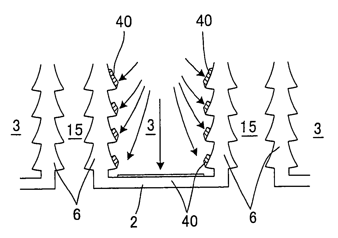
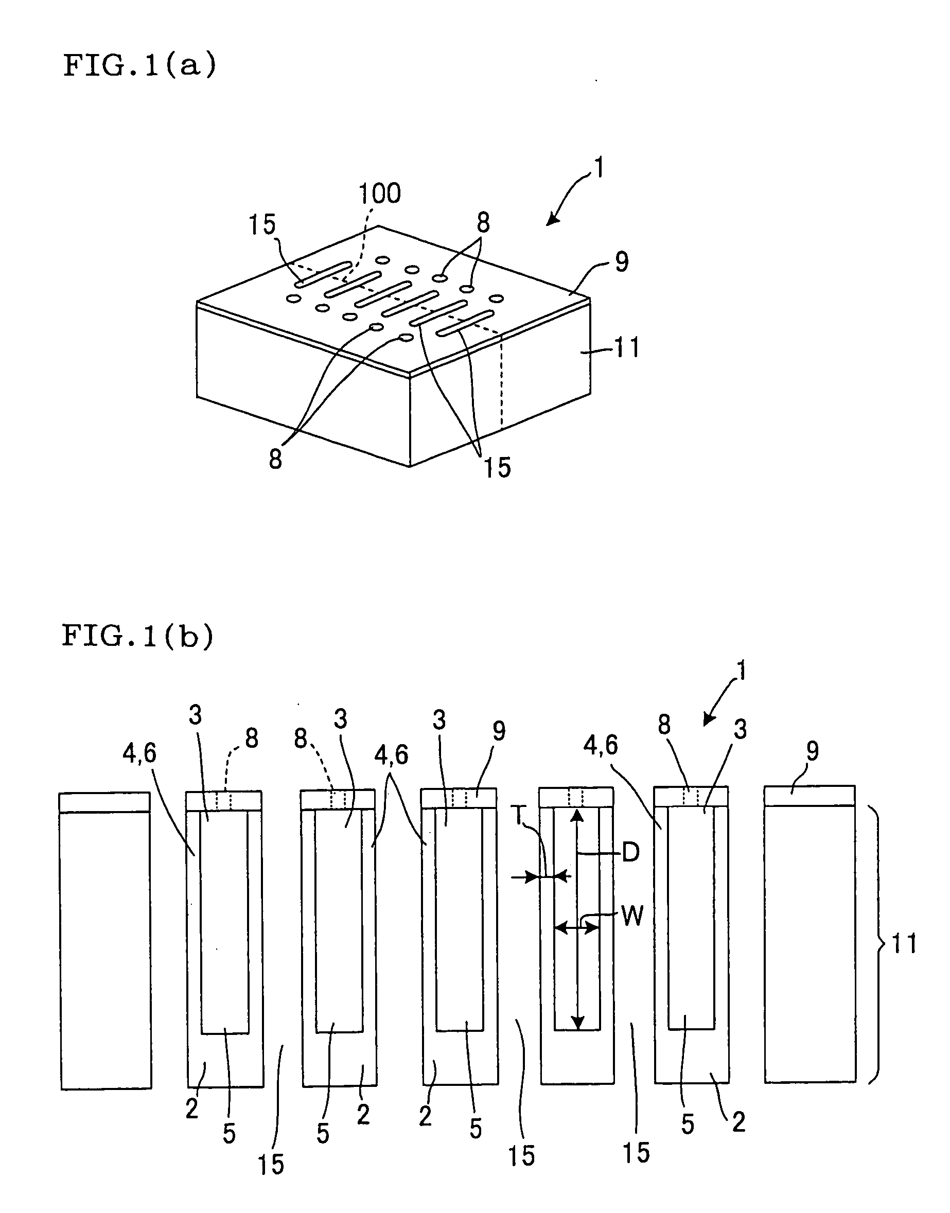
[0074] Piezoelectric / electrostrictive structures according to embodiments of the present invention and a method for manufacturing a piezoelectric / electrostrictive structure according to an embodiment of the present invention will now be described with reference to the accompanying drawings. It is to be understood that the present invention is not limited to the embodiments. Various modifications, variations, improvements, and replacements may be made based on the findings of those skilled in the art within the scope of the present invention. The accompanying drawings show preferable examples of the present invention. The present invention is not limited to the examples and information obtained from the drawings. In order to implement or verify the present invention, means identical or equivalent to those specified herein may be used and means described below are preferably used.

[0075] A piezoelectric / electrostrictive structure according to an embodiment of the present invention wil...


PUM

PropertyMeasurementUnit
widthaaaaaaaaaa
depthaaaaaaaaaa
aspect ratioaaaaaaaaaa

Abstract

A piezoelectric/electrostrictive structure includes a plurality of stacked sheet-shaped piezoelectric/electrostrictive bodies and at least one sheet of a thin film. The interfaces between the piezoelectric/electrostrictive bodies are exposed at side faces of the piezoelectric/electrostrictive structure, the side faces have notches, and at least one sheet of a thin film is placed on the notched portions of side faces. A method for manufacturing a piezoelectric/electrostrictive structure comprises stacking a plurality of ceramic green sheets made of a piezoelectric/electrostrictive material and firing the stacked ceramic green sheets to prepare fired piezoelectric/electrostrictive bodies and a step of forming at least one sheet of a thin film on side faces of the fired piezoelectric/electrostrictive bodies by a chemical vapor deposition process, the interfaces between the sheets are exposed at the side faces.

Description

BACKGROUND OF THE INVENTION [0001] 1. Field of the Invention [0002] The present invention relates to a piezoelectric / electrostrictive structure including a plurality of stacked sheet-shaped piezoelectric / electrostrictive bodies and also relates to a method for manufacturing such a structure by a green sheet-stacking process and a chemical vapor deposition (CVD) process. [0003] 2. Description of the Related Art [0004] It has been a long time since printing apparatuses such as printers, facsimiles, and copiers have used a non-impact process. In particular, most compact printers have recently used such a non-impact process; hence, clear images equivalent to silver photographs can be reproduced on sheets of paper with high-performance inkjet heads. Piezoelectric inkjet heads are typical components of non-impact printing apparatuses. The piezoelectric inkjet heads include actuators including a plurality of piezoelectric / electrostrictive actuating parts and discharge ink using the displac...

Claims


Application Information

Patent Timeline
Patent Type & Authority Applications(United States)
IPC IPC(8): B41J2/045B41J2/055B41J2/135B41J2/14B41J2/16H01L41/04H01L41/08H01L41/083H01L41/187H01L41/22H01L41/23
CPCB41J2/14209B41J2/1609B41J2/1631B41J2/1632H01L41/0831B41J2/1646H01L41/0533H01L41/23H01L41/273B41J2/1642B41J2/1606H10N30/883H10N30/501H10N30/02H10N30/053
Inventor OHMORI, MAKOTOKIMURA, KOJI
Owner NGK INSULATORS LTD
Why Eureka
Try Eureka