Jacking screw

A screw and jacking technology, applied in the direction of screws, bolts, nuts, etc., can solve the problems of the separation of the buckle, the disengagement and separation of the jacking screw, etc.

Inactive Publication Date: 2002-01-02
SOUTHCO
View PDF0 Cites 6 Cited by
  • Summary
  • Abstract
  • Description
  • Claims
  • Application Information

AI Technical Summary

Problems solved by technology

During the jacking operation, the buckle may separate and

Method used


Image

  • Jacking screw
  • Jacking screw
  • Jacking screw

Examples


Embodiment Construction

[0029] DESCRIPTION OF THE PREFERRED EMBODIMENT

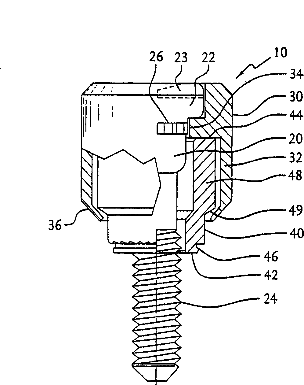
[0030] Reference is now made in detail to the drawings in which like numerals represent like elements throughout the several views. exist figure 1 A fixed jacking screw 10 according to a preferred embodiment of the present invention is shown in . The illustrated set jacking screw 10 generally comprises a screw 20 having a head 22 and a threaded shaft 24, a knob 30 preferably but optionally integral with the head of the screw 20, and a screw 20 mounted in standard fashion on the Collar 40 on first plate (not shown). The collar has a first end 42 and a second end 44 . The first end of the collar has a flat attachment means 46 which will be discussed in more detail below. The second end of the collar 40 is combined with the knob 30 and has means for securing the knob 30 (and therefore preferably the integral screw 20) to the collar 40, which enables the knob 30 and screw 20 to be positioned relative to the collar 40. The ring ...


PUM


Abstract

A jacking screw for attaching a first panel to a second panel which provides a force in the axial direction of the screw when the screw rotates in a first direction to jack the first panel down to the second panel and which provides a force in the axial direction of the screw with respect to the panel when the screw is rotated in the opposite direction to pry the first panel away from the second panel. The jacking screw has a screw, a ferrule surrounding and coaxial to the screw shaft, and a knob. The first end of the ferrule is attachable to a panel and the second end has an outwardly protruding annular step. The knob is attached to the head of the screw and Ahas a downwardly extending generally cylindrical portion, coaxial to the screw shaft and the ferrule and the downwardly extending cylindrical portion secures the knob to the ferrule allowing for rotational movement of the knob with respect to the ferrule but allowing substantially no axial movement of the knob with respect to the ferrule.

Description

Background of the invention [0001] The present invention generally relates to fasteners. More specifically, the present invention relates to fasteners of the type used to secure panels or modules to a receiving frame or housing requiring the aid of screws conventionally known as "jack screws". Eject the slab or module out. This type of jacking screw has been used in many applications. For example, it may be advantageous to use jacking screws mounted on a printed circuit board assembly within a housing. The use of one or more ejector screws is highly desirable if the printed circuit board assembly is inserted into a connector and greater force is required to extract the board from the connector. [0002] Some existing jacking screws use a retaining ring on the shaft of the screw to secure the screw in the housing mounted on the first plate. During the jacking operation, the clasp may separate and cause the jacking screws to come loose or otherwise separate. Summary of the...

Claims


Application Information

Patent Timeline
IPC IPC(8): F16B5/02F16B41/00
CPCF16B5/0208F16B41/002Y10S411/999
Inventor A·J·克雷利三世M·多布森
Owner SOUTHCO
Why Eureka
Try Eureka