Traverse controlling device

A control device and reciprocating motion technology, applied in transportation and packaging, conveying filamentous materials, thin material processing, etc., can solve the problems of inability to rotate at high speed, poor winding shape of the winding package, and large change rate of current command, etc. question

Inactive Publication Date: 2007-08-22
MURATA MASCH LTD
View PDF5 Cites 0 Cited by
  • Summary
  • Abstract
  • Description
  • Claims
  • Application Information

AI Technical Summary

Problems solved by technology

[0003] However, in the above-mentioned traverse device, the current flowing through the stator coil cannot always flow at the desired timing, and the maximum torque cannot always be applied to the rotor.
Therefore, it is impossible to maintain a high-precision position in the entire range of the traverse stroke, and there is a possibility that the winding shape of the winding package may be defective.
In addition, the above-mentioned traverse device has the problem that high-speed rotation cannot be performed due to insufficient torque, and a high-power traverse motor is required for high-speed rotation.
As the reason why the coil current cannot flow at the desired timing, there are several possibilities: a delay in the start of the current due to the influence of the inductance of the stator coil, or acceleration and deceleration when the necessary current amount (torque) becomes large. The rate of change of the current command becomes larger within the time

Method used


Image

  • Traverse controlling device
  • Traverse controlling device
  • Traverse controlling device

Examples


Embodiment Construction

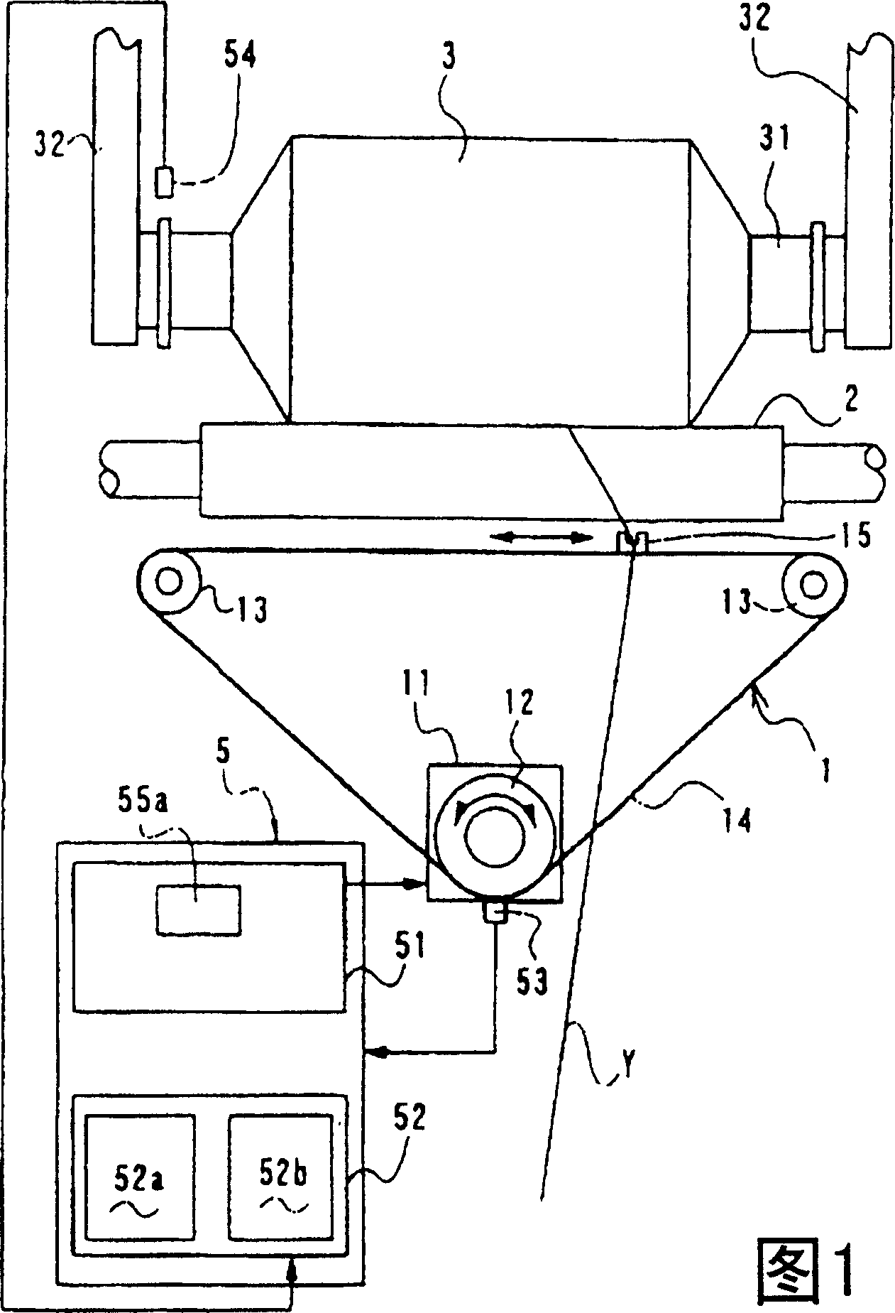
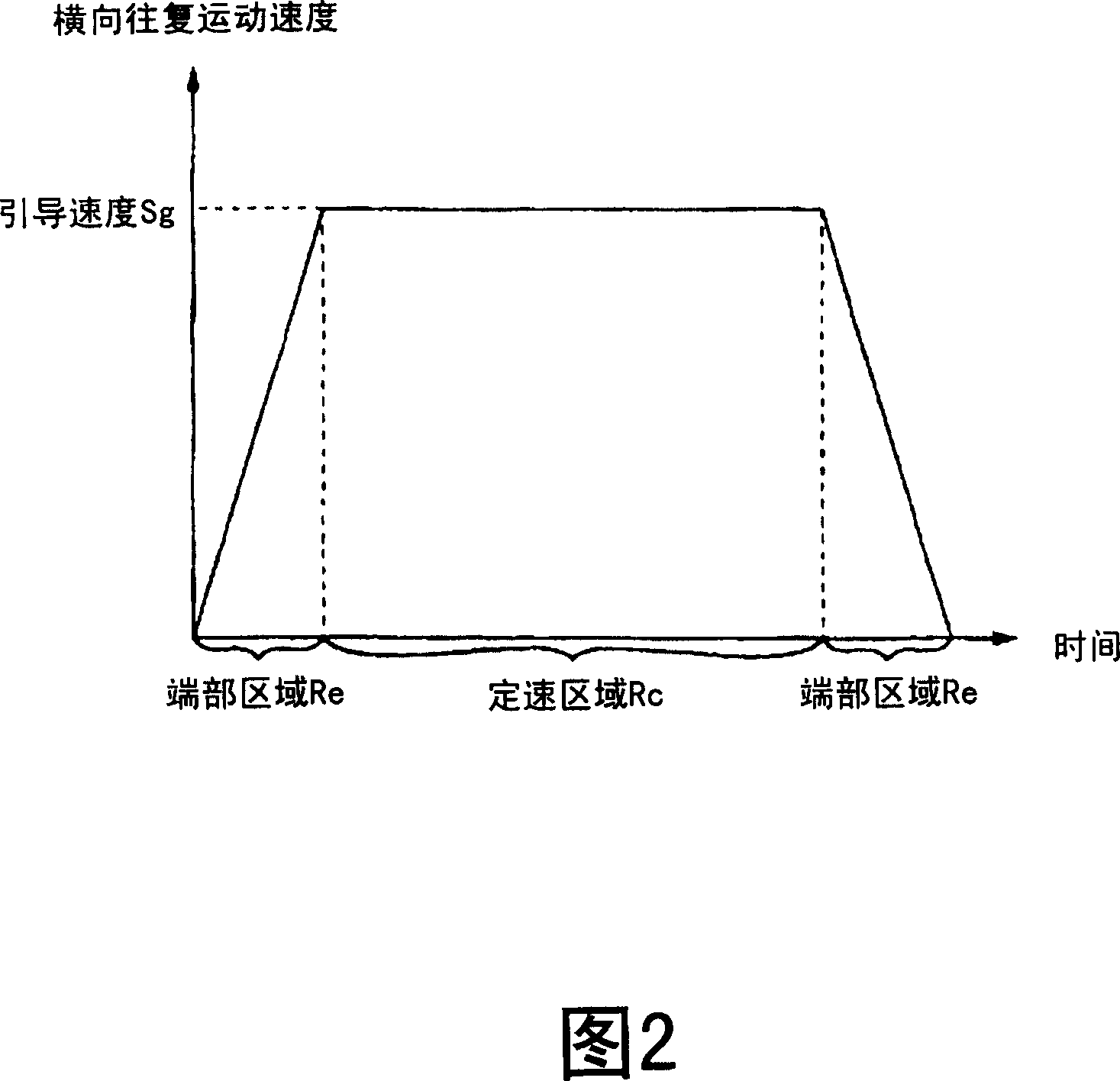
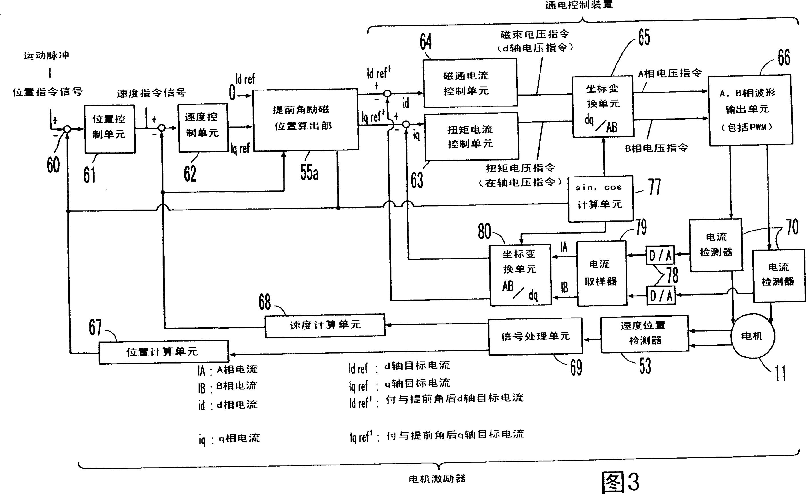
[0014] Embodiments of the present invention will be described with reference to the drawings. Fig. 1 is a schematic diagram of the overall composition of the traversing device of the present invention, Fig. 2 is a schematic diagram of the traversing speed at each traversing position in the traversing stroke, Fig. 3 is a schematic diagram showing the traverse motor used for vector control and advance angle control The block diagram of the composition of the motor actuator, Fig. 4 is a vector diagram illustrating the advance angle control with the motor rotation coordinates (d-q coordinates).

[0015] First, the configuration of a traverse device equipped with a traverse control device according to the present invention will be described. As shown in Fig. 1, the traversing device of the present application equipped with a traversing control device is applied to reciprocate the sliver Y unwound from the yarn feeding package not shown in the figure along the axial direction of the...


PUM


Abstract

There is a problem that, in a conventional traverse control device for making magnetic flux control of a traverse device, a current cannot follow correctly at the time of high speed driving because of many reasons such as the rising delay of an electric current by the inductance of a coil. The inventive traverse control device (5) for controlling the backward and forward drive of a transverse motor (11) in order to reciprocatingly move a transverse guide, includes: a speed positon detector (53) for detecting the present position of the rotor of the transverse motor (11); a spark-advance excitation position calculator (55a) for supplying electricity to a motor coil based on the present positon detected by the speed positon detector (53), after lapse of predetermined spark-advance time period from the present position detection time.

Description

technical field [0001] The present invention relates to a configuration of a traverse control device for controlling the position and speed of a traverse guide reciprocated by a traverse motor. Background technique [0002] In the previous single-spindle traversing device, the traversing yarn guides of each spindle were driven reciprocatingly by the traversing motor respectively. As such a single-spindle traversing device, as in Japanese Patent No. 2001-516319A (published on October 1, 1998), a magnetic flux control device is used to continuously generate the flux supplied to the traverse motor that drives the traverse guide. The voltage of the stator, whereby the rotational movement of the rotor of the traverse motor is controlled by the fixed stator flux generated by the stator voltage. Such a constitution is already known. [0003] However, in the above-mentioned traverse device, the current flowing through the stator coil cannot always flow at the desired timing, and t...

Claims


Application Information

Patent Timeline
Patent Type & Authority Patents(China)
IPC IPC(8): B65H54/28
CPCB65H2701/31B65H54/2821
Inventor 一阶朋之
Owner MURATA MASCH LTD
Why Eureka
Try Eureka