Rotating electric machine
A technology of rotating electrical machines and armatures, applied in synchronous motors with stationary armatures and rotating magnets, prefabricated windings embedded in motors, electromechanical devices, etc., can solve problems such as breakage and easy reduction of strength
- Summary
- Abstract
- Description
- Claims
- Application Information
AI Technical Summary
Problems solved by technology
Method used
Image
Examples
no. 1 approach
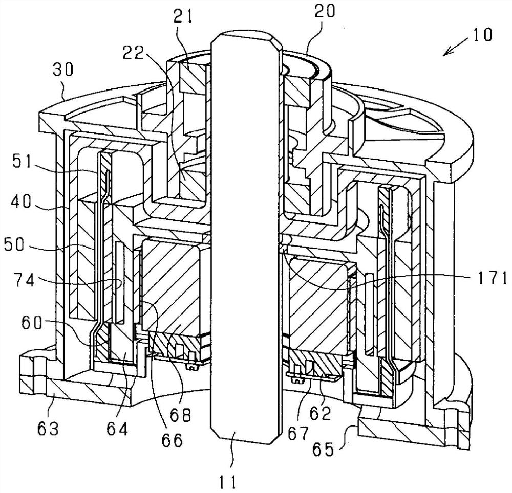
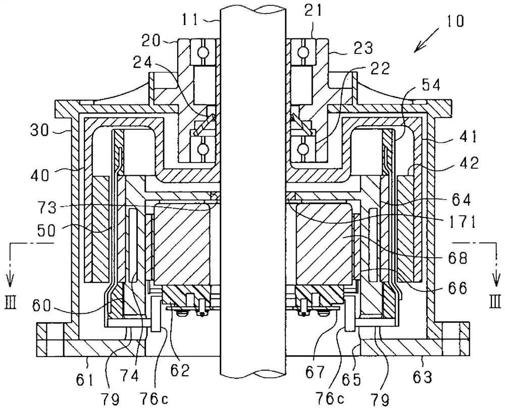
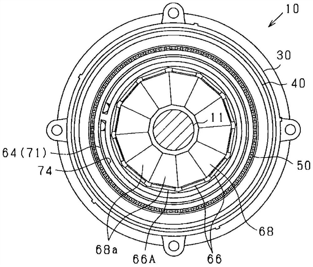
[0105] The rotating electric machine 10 of this embodiment is a synchronous multiphase AC motor and has an outer rotor structure (outer rotation structure). Figure 1 to Figure 5 The outline of the rotating electric machine 10 is shown. figure 1 is a vertical perspective view of the rotating electrical machine 10, figure 2 is a longitudinal sectional view of the rotating electrical machine 10 along the direction of the rotating shaft 11, image 3 is a cross-sectional view of the rotating electrical machine 10 in a direction perpendicular to the rotating shaft 11 ( figure 2 III-III line sectional view), Figure 4 is enlarged image 3 A section view of a part of Figure 5 is an exploded view of the rotating electrical machine 10 . In addition, in image 3 In FIG. 2 , for convenience of illustration, except for the rotating shaft 11 , hatching indicating a cut surface is omitted. In the following description, the direction in which the rotating shaft 11 extends is referr...
no. 2 approach
[0280] In the present embodiment, the polar anisotropy structure of the magnet unit 42 in the rotor 40 is changed, which will be described in detail below.
[0281] Such as Figure 22 and Figure 23 As shown, the magnet unit 42 is constructed using a magnet array called a Halbach array. That is, the magnet unit 42 has: the first magnet 131 whose magnetization direction (the direction of the magnetization vector) is the radial direction, and the second magnet 132 whose magnetization direction (the direction of the magnetization vector) is the circumferential direction. The first magnets 131 are arranged in the circumferential direction, and the second magnets 132 are arranged at positions between adjacent first magnets 131 in the circumferential direction. The first magnet 131 and the second magnet 132 are permanent magnets made of rare earth magnets such as neodymium magnets, for example.
[0282] The first magnets 131 are arranged apart from each other in the circumferenti...
Deformed example 1
[0296] In the above-described embodiment, the outer peripheral surface of the stator core 52 is formed into a curved surface without unevenness, and the plurality of lead wire groups 81 are arranged side by side at predetermined intervals on the outer peripheral surface, but this may be changed. For example, if Figure 25 As shown, the stator core 52 has an annular yoke 141 and a protruding portion 142. The yoke 141 is provided on the opposite side to the rotor 40 (the lower side in the figure) on both radial sides of the stator winding 51. The protruding portion 142 extends from the yoke portion 141 to protrude between the linear portions 83 adjacent in the circumferential direction. The protrusions 142 are provided at predetermined intervals on the radially outer side of the yoke 141 , that is, on the side of the rotor 40 . Each lead wire group 81 of the stator winding 51 engages with the protruding portion 142 in the circumferential direction, and the protruding portion 14...
PUM
| Property | Measurement | Unit |
|---|---|---|
| saturation flux density | aaaaa | aaaaa |
| thermal resistance | aaaaa | aaaaa |
Abstract
Description
Claims
Application Information
 - R&D
- Intellectual Property
- Life Sciences
- Materials
- Tech Scout
- Unparalleled Data Quality
- Higher Quality Content
- 60% Fewer Hallucinations
Browse by: Latest US Patents, China's latest patents, Technical Efficacy Thesaurus, Application Domain, Technology Topic, Popular Technical Reports.
© 2025 PatSnap. All rights reserved.Legal|Privacy policy|Modern Slavery Act Transparency Statement|Sitemap|About US| Contact US: help@patsnap.com


