Synchronous motor of permanent magnet

A synchronous motor and permanent magnet technology, applied in synchronous motors with stationary armatures and rotating magnets, magnetic circuit rotating parts, magnetic circuit static parts, etc., can solve the problem of permanent magnet magnetic flux drop, torque drop, etc. problems, achieve excellent results, and expand the effect of high-speed operation range

Active Publication Date: 2013-06-26
HITACHI LTD
View PDF2 Cites 0 Cited by
  • Summary
  • Abstract
  • Description
  • Claims
  • Application Information

AI Technical Summary

Problems solved by technology

[0007] As mentioned above, in the permanent magnet synchronous motor, it is effective to reduce the inductance in order to realize the expansion of the high-speed rotation area. It is easy to cause magnetic saturation, which leads to the decrease of the magnetic flux generated by the permanent magnet and the problem of the decrease of the torque.

Method used


Image

  • Synchronous motor of permanent magnet
  • Synchronous motor of permanent magnet
  • Synchronous motor of permanent magnet

Examples


Embodiment 1

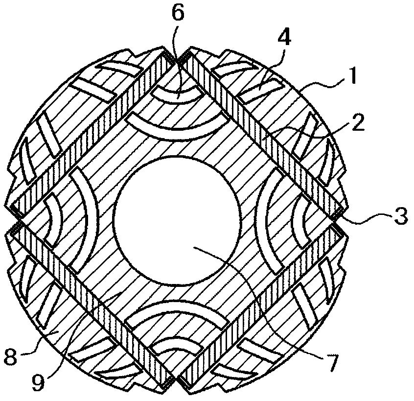
[0080] image 3 It is a radial sectional view of the rotor of the permanent magnet synchronous motor according to the first embodiment of the present invention. and, Figure 4 is a schematic diagram of the magnetic flux lines in the radial section of the permanent magnet synchronous motor according to the first embodiment of the present invention, Figure 5 is used to illustrate the above image 3 Radial sectional view of the rotor with the indicated permanent magnet widths and slot widths provided on the rotor back yoke, Image 6 Indicates the slit width W of this example sl / W pm With no load induced electromotive force E o , Torque M p and q-axis inductance L q Relationship.

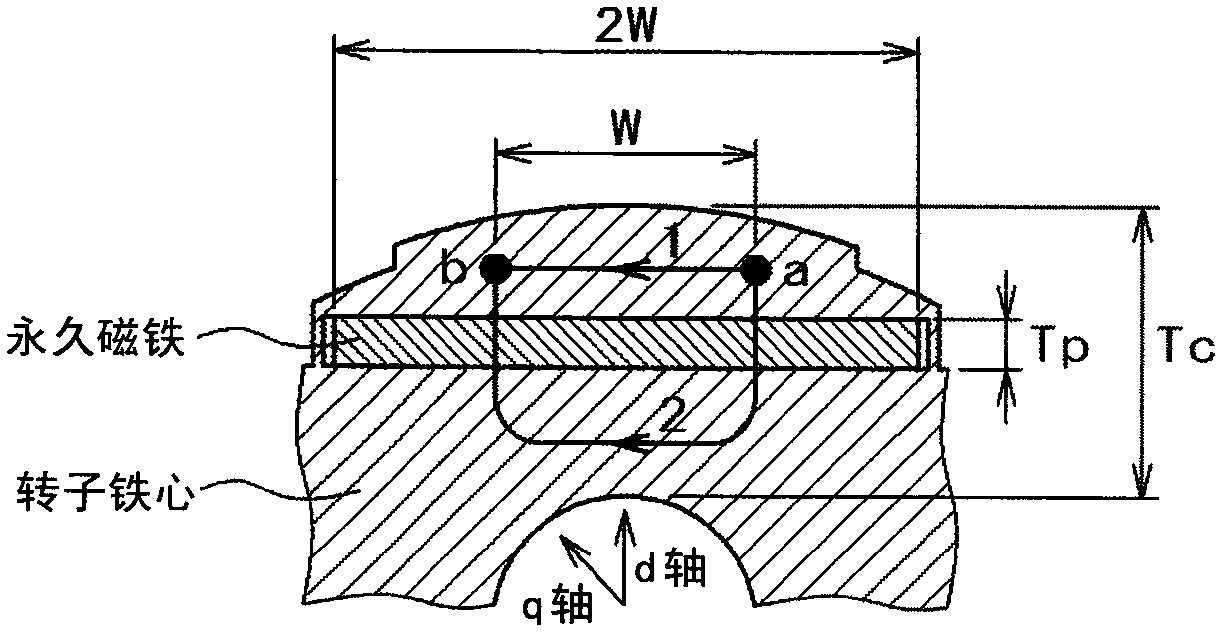
[0081] in the image 3 Among them, the rotor 1 is composed of laminated steel plates, and transmits power to the outside through the output shaft inserted into the shaft hole 7 . Inside the rotor 1, the permanent magnets 2 embedded in the magnet insertion holes 3 are arranged as four poles, a...

Embodiment 2

[0101] Next, Figure 8 It is a radial sectional view of the rotor of the permanent magnet synchronous motor according to the second embodiment of the present invention. in the Figure 8 , against the above image 3 The same structural elements are also attached with the same symbols to avoid repeated explanations.

[0102] It should be noted that the Figure 8 The structure shown is the same as the above figure 1 The difference of the shown structure is that the permanent magnet 2 is arranged in six poles, and among the slits 6a to 6d provided four times per pole, the width of the slits 6b and 6c located near the center of the magnetic poles is wider than that of the slits 6a to 6d located at the center of the magnetic poles. Slits 6a, 6d near the ends. In addition, in the illustrated example, no slit is provided in the outer peripheral core portion 8 , however, the present invention is not limited thereto, and the slit may be provided in the outer peripheral core portio...

Embodiment 3

[0104] Figure 9 It is a radial sectional view of the rotor of the permanent magnet synchronous motor according to the third embodiment of the present invention. in the Figure 7 , against the above image 3 The same structural elements are attached with the same symbols to avoid repeated explanations.

[0105] Should Figure 9 The structure shown in Embodiment 3 is the same as the above figure 1 The difference of the shown structure is that there are six slits per pole, and the distance between adjacent slits 6e and 6f located near the center of the magnetic pole among the slits 6a to 6f is smaller than that at the end of the magnetic pole. The distance between adjacent adjacent slits 6a, 6b or the distance between slits 6c, 6d. By adopting such a structure, the effect of reducing the inductance can be further increased. Furthermore, the third embodiment is not limited to the 4-pole motor, and the same effect can be obtained with the same structure in the 6-pole motor,...


PUM


Abstract

The invention discloses a synchronous motor of permanent magnet which is characterized by not decreasing the torque but enlarging the high speed running range, when using the rare earth magnet; the synchronous motor of permanent magnet is provided with a rotor (1) and a stator (100); the rotor (1) is used for collocating 2n poles (n is a natural number) in a circular shape; the stator (100), which is arranged opposite to the rotor (1) with a gap therebetween, is capable of generating rotary flux, wherein the rotor is as follows: at least one permanent magnet mainly made of rare earth is embedded in an iron core of every pole so as to consist of a field pole; the thickness Tp of the permanent magnet is smaller than one third of the thickness Tc of the iron core of the rotor; a plurality ofnarrow gaps composed of non-magnetic bodies are arranged on the iron cores which are arranged between the permanent magnets of adjacent and different magnet poles of the rotor.

Description

technical field [0001] The present invention relates to a permanent magnet synchronous motor, and more particularly to a permanent magnet synchronous motor using a rare earth magnet typified by a neodymium magnet. Background technique [0002] When the permanent magnet synchronous motor is rotated at high speed, the voltage of the inductor drops greatly in proportion to the rotational speed, so the upper limit of the rotational speed is limited within a range where the input voltage does not become insufficient. For the purpose of expanding the high-speed rotation area, such as the following Patent Document 1 (especially its Figure 4 ), there is known a technique of reducing inductance by providing slits in the outer peripheral core portion outside the permanent magnet embedded in the rotor and the back yoke portion inside the permanent magnet. [0003] On the other hand, in rare earth magnets such as neodymium magnets, the residual magnetic flux density is 1T or more, and ...

Claims


Application Information

Patent Timeline
Patent Type & Authority Patents(China)
IPC IPC(8): H02K21/14H02K1/27H02K1/14
Inventor 高桥晓史
Owner HITACHI LTD
Why Eureka
Try Eureka