A one-way power conversion device with a swinging and rotating housing and a method for realizing the one-way power conversion

A rotating shell and power conversion technology, which is applied to transmission devices, mechanical equipment, belts/chains/gears, etc., can solve the problems of low energy absorption and conversion efficiency, insufficient ability to resist natural disasters, and high manufacturing costs. Clutches, cost and maintenance costs are low, and the effect of long service life

Active Publication Date: 2021-02-02
吴钦发
View PDF1 Cites 0 Cited by
  • Summary
  • Abstract
  • Description
  • Claims
  • Application Information

AI Technical Summary

Problems solved by technology

The sea has inexhaustible and inexhaustible "green" renewable energy. In the past century, many countries have invested a lot of money and talents in the research and development of ocean power generation. However, most of today's ocean power generation equipment has factors such as low energy absorption and conversion efficiency, high manufacturing cost, and insufficient ability to resist natural disasters, which has caused the ocean power industry to fail to enter industrial development for a long time
[0003] Chinese Invention Patent No. 201010561662.8 is titled a wave power generation method and a system for implementing the method. This invention uses a float to swing and float under the action of waves to drive a one-way conversion device to perform one-way rotation power generation. Although the power generation disclosed in this invention The method and the system implementing this method can better use the wave energy to directly drive the generator assembly to generate electricity in the form of mechanical energy, but in the ocean, due to the instability of the direction of the wave energy, it can only absorb the back and forth kinetic energy of the wave in one direction, and due to The active upward fluctuation of the wave has a certain inertial force, and its kinetic energy is relatively large, while downward is a natural return, and its kinetic energy is relatively small. The kinetic energy of the two swinging forces is different. To absorb this kinetic energy more comprehensively, it must be considered in different Swing direction to set different transmission ratios

Method used


Image

  • A one-way power conversion device with a swinging and rotating housing and a method for realizing the one-way power conversion
  • A one-way power conversion device with a swinging and rotating housing and a method for realizing the one-way power conversion
  • A one-way power conversion device with a swinging and rotating housing and a method for realizing the one-way power conversion

Examples


Embodiment approach

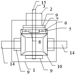
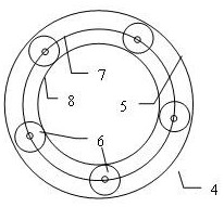
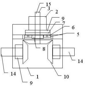
[0047] The planetary gear assembly 4 includes: the sun gear 8, which is connected with the power output shaft 3; the outer ring gear 5, which is connected with the oscillating rotating housing 1; the planetary gear set 6, which meshes with the outer ring gear 5 and the sun gear 8 at the same time Planetary carrier 7, which supports the planetary gear set 6 and connects the overrunning clutch 9 at the same time; when the oscillating rotating housing 1 drives the outer ring gear 5 to rotate in reverse, the overrunning clutch 9 reversely stops the supporting shaft 2 of the oscillating rotating housing to drive the sun gear 8 And the power take-off shaft 3 rotates forwardly. In addition, in this embodiment, the one-way power conversion device provided by the present invention with a swinging rotating housing 1 has been described, but the present invention is not limited to this embodiment. For example, the installation position of the overrunning clutch 9 can be at the Between the...

Embodiment 1

[0053] refer to Figure 1 to Figure 4 As shown, in a specific embodiment of the present invention, the structure of the one-way power conversion device with single swing power input is as follows:

[0054] First of all, it includes a swinging rotating housing 1, a swinging rotating housing support shaft 2, a power output shaft 3, a first one-way device 11 and a second one-way device 12 ( Figure 7 shown in ), the swing rotating housing support shaft 2 and the power output shaft 3 are coaxially arranged, a part of the swing rotating housing support shaft 2 and the power output shaft 3 is located in the swing rotating housing 1, and the other part is located in the swing rotating housing 1 in vitro.

[0055] The oscillating rotating housing support shaft 2 is fixedly connected to the external support frame, which supports the oscillating rotating housing 1 and acts as a reaction force to the planetary gear assembly. combine image 3 with Figure 4 , the first one-way device ...

Embodiment 2

[0071] Please refer to Figure 8 , in another specific embodiment of the present invention, the structure of the double-swing one-way power conversion device is as follows:

[0072] The swing input shaft 14 of the second one-way power conversion device is connected with the overrunning clutch 9 of the second one-way device 12, and transmits power to the power output wheel.

[0073] The power output wheel of reverse rotation motion is connected with the outer ring gear 5, and the rotation of the power output wheel of reverse rotation motion drives the outer ring gear 5 to rotate.

[0074] The outer ring gear 5 meshes with the planetary gear set 6 , the planetary gear set 6 meshes with the planetary carrier 7 and the sun gear 8 respectively, and the planetary carrier 7 is connected with the overrunning clutch 9 of the first one-way device 11 .

[0075] The sun gear 8 is connected with the power output shaft 3 .

[0076] The power take-off wheel that rotates in the forward dire...


PUM


Abstract

The invention provides a one-way power conversion device with a swinging and rotating housing and a method for realizing the one-way power conversion. The one-way power conversion device includes a swinging and rotating housing support shaft, a power output shaft, and a first one-way device And the second one-way device, the device includes one or more one-way power conversion devices combined with each other, and forms a universal swing power that can absorb and convert this swing power into one-way usable rotary power. The invention provides a one-way power conversion device with a swinging and rotating housing, which can absorb swinging power in any direction, and has the advantages of high absorption and conversion efficiency, low manufacturing and maintenance costs, strong stability, and wide application range.

Description

technical field [0001] The invention relates to the technical field of power conversion, in particular to a one-way power conversion device with a swinging and rotating housing and a method for realizing the one-way power conversion. Background technique [0002] It is the common goal of all mankind to effectively apply kinetic energy, especially to obtain more irregular green energy in nature. The sea has inexhaustible and inexhaustible "green" renewable energy. In the past century, many countries have invested a lot of money and talents in the research and development of ocean power generation. However, most of today's ocean power generation equipment has factors such as low energy absorption and conversion efficiency, high manufacturing cost, and insufficient ability to resist natural disasters, which has caused the ocean power industry to fail to enter industrial development for a long time. [0003] Chinese Invention Patent No. 201010561662.8 is titled a wave power gen...

Claims


Application Information

Patent Timeline
Patent Type & Authority Patents(China)
IPC IPC(8): F16H37/02
CPCF16H37/02Y02E10/30
Inventor 吴钦发
Owner 吴钦发
Why Eureka
Try Eureka