Uniform speed flow sensor having flow signal amplifying function

A flow sensor and flow signal technology, which is applied in the direction of detecting fluid flow by measuring pressure difference, volume/mass flow generated by mechanical effects, etc., can solve the problems of measurement signal fluctuation, small measurement signal, low sensitivity, etc., to eliminate fluctuations, The effect of large measurement signal and high measurement sensitivity

Inactive Publication Date: 2007-08-22
温汉璋
View PDF8 Cites 0 Cited by
  • Summary
  • Abstract
  • Description
  • Claims
  • Application Information

AI Technical Summary

Problems solved by technology

[0003] The present invention overcomes the problems of small measuring signal, low sensitivity and fluctuating measuring signal existing in the prior art

Method used


Image

  • Uniform speed flow sensor having flow signal amplifying function
  • Uniform speed flow sensor having flow signal amplifying function

Examples


Embodiment 1

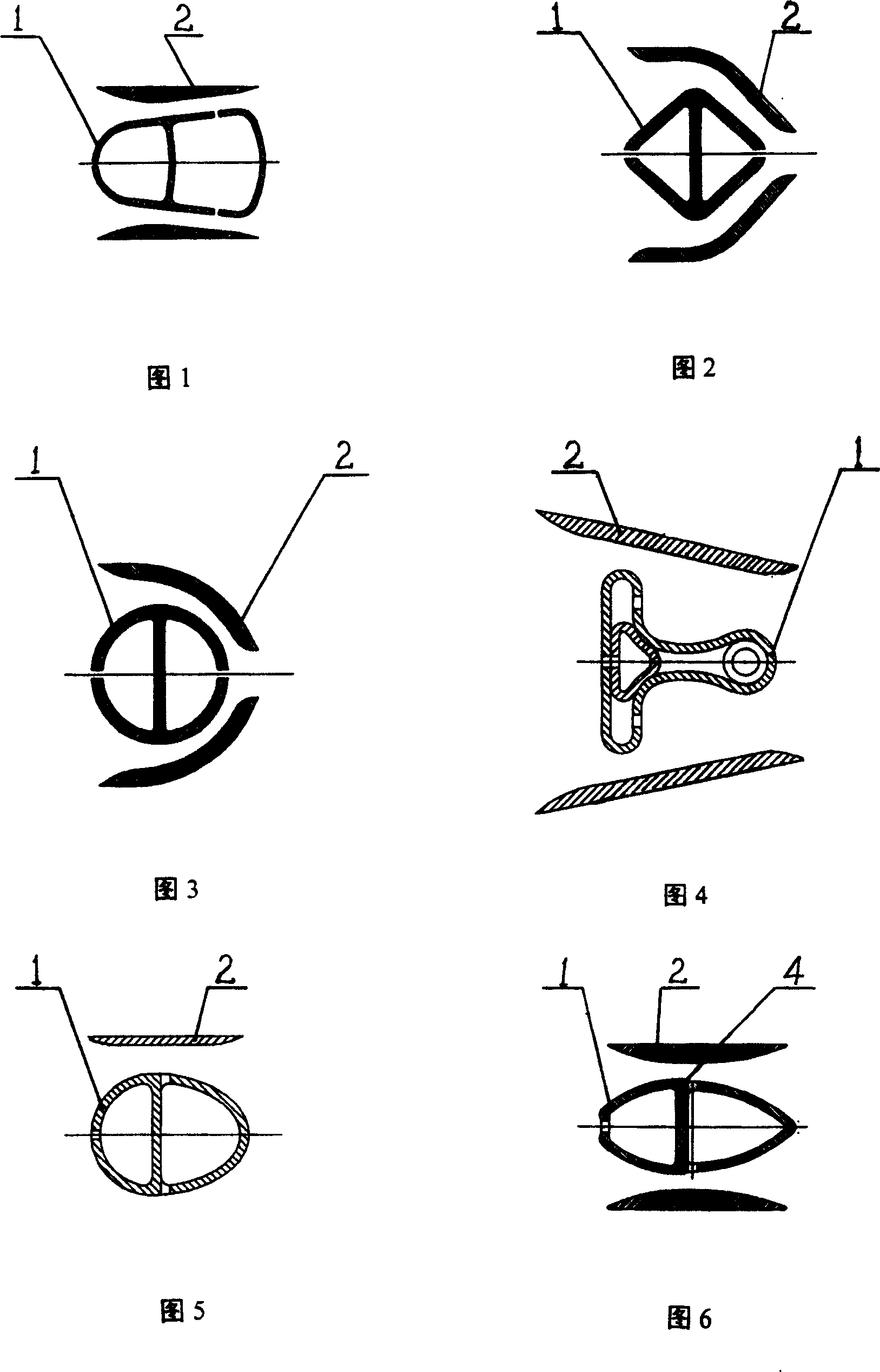
[0033] Referring to Fig. 1, the above-mentioned measuring rod 1 is in the shape of a Verabar bullet, and both sides of its symmetrical plane are provided with speed-up plates 2, which are arranged symmetrically, and the projection of the speed-up board 2 on the measuring rod 1 covers the measuring rod 1. superior. The inner side of the cross-section of the speed-increasing plate 2 is a combination of a protruding arc and a straight line, and the straight line is parallel to the surface of the static pressure-taking hole area on the measuring rod 1, so that the static pressure-taking hole is located at the speed-raising plate 2 and the measuring rod 1. In the minimum static pressure zone; the outside of said speed-up plate 2 section is a straight line.

Embodiment 2

[0036] See Figure 2: the above-mentioned measuring rod 1 is diamond-shaped, and the two sides of its symmetrical plane are provided with speed-increasing plates 2. The speed-increasing plates 2 are arranged symmetrically. The plate 2 is slightly extended on one side of the static pressure taking hole, so that the static pressure taking hole is located in the minimum static pressure zone formed by the speed increasing plate 2 and the measuring rod 1 . The inner side of the cross-section of the speed-increasing plate 2 is a concave streamline corresponding to the surface of the measuring rod 1, and the streamline can be formed by a protruding arc at both ends, a concave arc in the middle, and two straight lines between the arcs. Said that the outside of speed-up plate 2 cross-sections is streamlined corresponding to its inside.

Embodiment 3

[0038] Referring to Fig. 3, the above-mentioned measuring rod 1 is circular, and both sides of its symmetrical plane are provided with speed-increasing plates 2. The speed-increasing plates 2 are arranged symmetrically. The plate 2 is slightly extended on one side of the static pressure taking hole, so that the static pressure taking hole is located in the minimum static pressure zone formed by the speed increasing plate 2 and the measuring rod 1 . The inner side of said speed-up plate 2 cross-section is a streamline shape formed by three sections of arcs, the three sections of arcs are concave in the middle and convex at both ends, and the outside of said speed-up plate 2 cross-section is formed by one section of arc.


PUM


Abstract

This invention relates to one device to measure flux and in detail to one even speed flux sensor with signal amplifying function. The invention has the technique program as the following: adopting one even speed flux sensor comprising measurement bar with gross access hole and static access hole, which is characterized by the following: the symmetric surface side of the bar and the bar are located with one static access flux speed board fixed along the bar outside through fixing part along its length direction.

Description

Technical field: [0001] The invention relates to a device for measuring fluid flow, in particular to an average velocity flow sensor with the function of amplifying flow signals. Background technique: [0002] Because when the fluid flows along the outer surface of the measuring rod, the flow velocity increases and the static pressure decreases, and the resulting dynamic and static pressure difference depends on the flow velocity and the profile of the measuring rod. When the fluid velocity is relatively small, the existing products have the problems of small measurement signal and low sensitivity; if the flow field is unstable, the measurement signal will fluctuate. Invention content: [0003] The invention aims to overcome the problems of small measuring signal, low sensitivity and fluctuating measuring signal in the prior art. [0004] In order to solve the problems existing in the prior art, the technical solution of the present invention is that a constant velocity f...

Claims


Application Information

Patent Timeline
Patent Type & Authority Patents(China)
IPC IPC(8): G01F1/36
Inventor 温汉璋
Owner 温汉璋
Why Eureka
Try Eureka